OWNER’S MANUAL
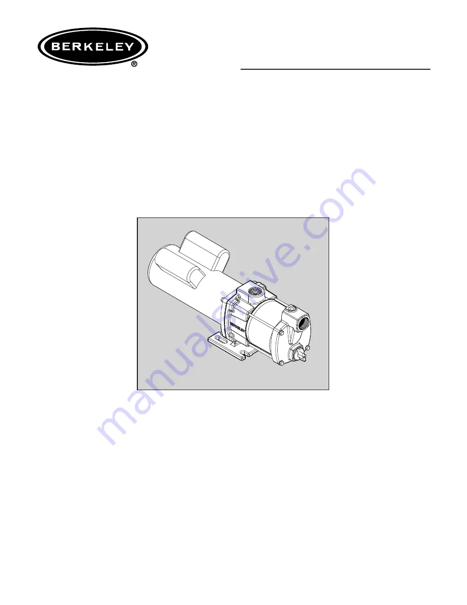
Self-Priming Horizontal Multistage Pump
Installation/Operation/Parts
For further operating, installation, or maintenance assistance:
Call 1-888-237-5353
© 2007
BE682 (Rev. 12/3/08)
SSHM-2
293 Wright St., Delavan WI 53115
Страница 1: ...L Self Priming Horizontal Multistage Pump Installation Operation Parts For further operating installation or maintenance assistance Call 1 888 237 5353 2007 BE682 Rev 12 3 08 SSHM 2 293 Wright St Dela...
Страница 2: ...power lines Make workshops childproof use padlocks and master switches remove starter keys Do not touch an operating motor Modern motors can operate at high temperatures To avoid burns when servicing...
Страница 3: ...erter will void the warranty Note also that three phase motors must be protected by three leg ambient compensated extra quick trip overload relays of the recommended size or the warranty is void Your...
Страница 4: ...g Leave room to use wrenches 8 Pump body may explode if used as a booster pump DO NOT use in a booster application NOTICE Use the installation method on page 5 which matches your well type 9 Install a...
Страница 5: ...ipe Flow arrow on check valve must point toward pump HORIZONTAL PIPING FROM WELL TO PUMP 1 Never install a suction pipe that is smaller than the suction port of the pump 2 To aid priming on well point...
Страница 6: ...electrical power supply Failure to ground motor can cause severe or fatal electrical shock hazard Do not ground to a gas supply line To avoid dangerous or fatal electrical shock turn OFF power to moto...
Страница 7: ...ated fittings 6 Protect current carrying and grounding conductors from cuts grease heat oil and chemicals 7 Connect current carrying conductors to terminals L1 and L2 under motor canopy single phase o...
Страница 8: ...ith water before starting 1 Remove priming plug Figure 13 2 Make sure suction and discharge valves and any hoses on discharge side of pump are open 3 Fill pump and suction pipe with water 4 Replace pr...
Страница 9: ...nnect the suction line 5 Remove four capscrews Key No 18 from the pump see Figure 17 6 Pull the pump suction body forward see Figure 18 Remove the sleeve Key No 9 by pulling it straight forward Be car...
Страница 10: ...dirt foreign particles scratches and grease 7 Inspect the shaft to be sure it is free of nicks and scratches PUMP REASSEMBLY 1 Bolt the bracket down to the foundation see Figure 23 2 Slide the motor...
Страница 11: ...ine and shaft seal 2 Water level below suction pipe inlet 2 Lower suction line into water and re prime If receding water level in well exceeds 20 6 1M a deep well pump is needed Foot valve or strainer...
Страница 12: ...Key Nos 6 8 and 10 14 6 Shaft Seal 1 U9 6 U9 6 7 Spacer 1 121P1710 121P1710 8 O Ring 2 111P2700 111P2700 9 Sleeve 1 251A4310 251A4310 10 Diffuser 4 101P4790 101P4790 11 Impeller 4 101P2070 101P2070 1...