09.10.03
Operating Instructions
SIOC03_GB
Serial Input/Output Converter SIOC03
9
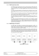
These handshaking connections are present for software or hardware that requires full
handshaking. Use of BERGES software on most computers does not require the full hand-
shaking, and operation may be accomplished by proper connection of only the GND, RTS,
TxD and RxD signals.
Transmission of data is enabled by raising the RTS signal prior to sending data on the TxD
line. The transmitter is enabled with 20 microseconds of the RTS assertion.
6
Troubleshooting
6.1
Introduction
This chapter provides information on using the LEDs incorporated into the design of the
SIOC03 as troubleshooting aids.
6.2
Troubleshooting Tips
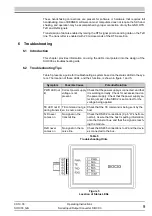
Table 5 presents a guide for troubleshooting a system based on the status LEDs in the sys-
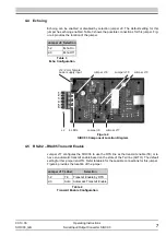
tem. The location of these LEDs, and their function, is shown in figure 1 and 5.
Symptom
Possible Cause
Potential Solution
PWR LED not
lit
Correct power supply
voltage is not
present.
Check that the power supply is connected, and that
it is working correctly. Check for excessive load on
the power supply. Check that the power supply se-
lection jumper in the SIOC2 is set correct for the
voltage being applied.
TE LED not lit
during transmit
TE command not giv-
en in source code.
Check that the TE command is being sent by the
host.
TxD never
comes on
No signal on the
transmit line.
Check the RS232 connections (9 pin “D” shell con-
nector). Assure that the host is putting information
onto the transmit bus, and that the signal is reach-
ing the module.
RxD never
comes on
No signal on the re-
ceive line.
Check the RS485 connections to J2 and the devic-
es connected to the bus.
Table 5
Troubleshooting Hints
Figure 5
Location of Status LEDs
Содержание SIOC03
Страница 1: ...Operating Instructions Serial Input Output Converter SIOC03 ...
Страница 2: ......
Страница 13: ......


