


13
ENGLISH
The user interface allows the operating performance to be viewed (operating
status and alarm status) and it also allows the circulator operating modes
to be set.
The performance, indicated by the LEDs (
B
) and (
C
) is always visible during
normal operation of the circulator whereas the settings can be carried out
by pressing the button (
A
).
3.12.2 Operating status indication
When the circulator is in operation the LED (
B
) is green. The four yellow
LEDs (
C
) indicate the electrical energy consumption (P1) as shown in the
following table.
LED status
CIRCULATOR status
Consumption in
% of MAX P1 (*)
Green LED on +
1 yellow LED on
Operating at minimum
0~25
Green LED on +
2 yellow LEDs on
Operating at
minimum-medium
25~50
Green LED on +
3 yellow LEDs on
Operating at medium-
maximum
50~75
Green LED on +
4 yellow LEDs on
Operating at maximum
100
(*) For the power (P1) absorbed by the circulator see the indications in the
“Technical Data” table.
3.12.3 Alarm status indication
If the circulator has detected one or more alarms the two-coloured LED (
B
)
will be red. The four yellow LEDs (
C
) indicate the type of alarm as shown
in the following table.
LED status
ALARM
description
Status
CIRCULATOR
Possible
SOLUTION
Red LED on +
1 yellow LED
on (LED 5)
The drive shaft
is jammed
Start attempt
every 1.5
seconds
Wait or unjam
the drive shaft
Red LED on +
1 yellow LED
on (LED 4)
Low input
voltage
Warning only.
The circulator
continues to
operate
Check the
input voltage
Red LED on +
1 yellow LED
on (LED 3)
Electrical power
supply fault or
faulty circulator
The circulator
is stopped
Check the
electrical power
supply or replace
the circulator
b
If there are several alarms the circulator will display only the alarm
with the highest priority.
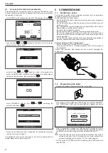
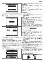
3.12.4 Display of active settings
With the circulator powered, press briefly on the button (
A
) to view the active
configuration of the circulator. The LEDs indicate the active settings.
In this phase no variations can be made to the circulator configuration. Two
seconds after the button (
A
) has been pressed the user interface returns to
the normal operating status display.
3.12.5 Key lock function
The purpose of the key lock function is to prevent accidental modifications
to the settings or the improper use of the circulator.
When the key lock function is activated, long-pressing the button (
A
) is
prevented. This prevents the user from entering the circulator’s operating
modes setting section.
Enabling/disabling the key lock function is achieved by pressing the button
(
A
) for more than 10 seconds. During this step all of the LEDs (
C
) will flash
for 1 second.
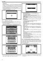
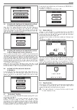
3.12.6 Changing the operating mode
In normal operating conditions the circulator works with the factory settings
or the last settings carried out.
To change the configuration:
Ensure that the key lock function is deactivated.
Press the button (
A
) for more than 2 seconds until the LEDs begin to flash.
Short-press the button (
A
) within 10 seconds and the user interface will move
on to display the next settings. The various available settings will appear in
a cyclic sequence.
If the button (
A
) is not pressed, the last setting will be stored.
A
B
C
A. Operating status display
B. Settings display
C. Settings
Configuración
If the button (
A
) is pressed you can move back to the “active settings display”
again and check that the LEDs (
B
) and (
C
) indicate (for 2 seconds) the last
setting carried out.
If the button (
A
) is not pressed for more than 2 seconds the user interfaces
switches to the “Operating status display”.
The available settings are shown in figure along with the related representation
of LED (
B
) and (
C
).
(*)
LED 1
R
LED 2
G
LED 3
G
LED 4
G
LED 5
G
(*) Factory set value
R red
G yellow
Содержание EXCLUSIVE C
Страница 101: ... ...


