CHROMOPHARE
®
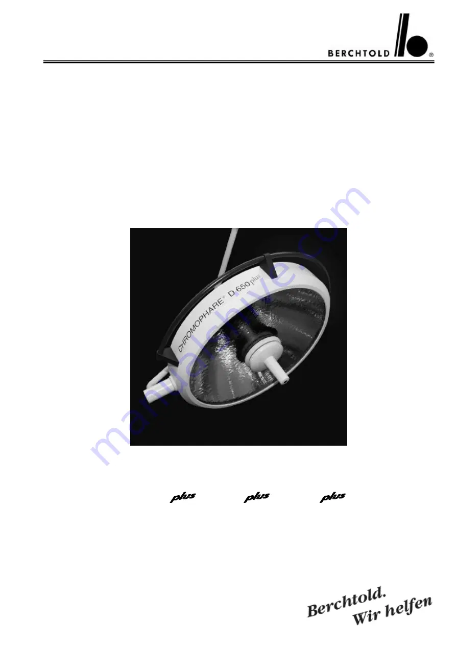
D 650
, D 530
, D 500
D 650, D 530, D 500
Service Manual (E)
Single Light and Combination Light
Страница 1: ...CHROMOPHARE D 650 D 530 D 500 D 650 D 530 D 500 Service Manual E Single Light and Combination Light ...
Страница 2: ...OMOPHARE D 500plus D 500 classic cardanic 13 3 1 6 CHROMOPHARE D 500plus D 500 flat cardanic 13 3 2 Notes on operation 14 21 3 2 1 Setting the control unit functions 14 17 3 2 1 1 CHROMOPHARE D 650plus D 650 14 15 3 2 1 2 CHROMOPHARE D 530plus D 530 16 17 3 2 1 3 CHROMOPHARE D 500plus D 500 17 3 2 2 Adjusting the field size with the sterizable hand grip 18 3 2 3 Adjusting the field size light fiel...
Страница 3: ...50 51 8 5 CHROMOPHARE D 650plus D 650 version Standard without EndoLite 51 8 6 CHROMOPHARE D 650plus D 650 version light field plotting model LFN 52 55 8 7 CHROMOPHARE D 650plus D 530plus D 650 D 530 version with EndoLite 55 56 8 8 CHROMOPHARE D 530plus D 500plus D 530 D 500 56 57 8 9 CHROMOPHARE D 530plus D 530 version Standard and EndoLite 58 8 10 CHROMOPHARE D 500plus D 500 version Standard 59 ...
Страница 4: ... 500plus D 530 D 500 Power supply mounted in a cut out cabinet 79 14 9 CHROMOPHARE D 530plus D 530 Control unit in power box mounted separately from the OR Light 80 14 10 CHROMOPHARE D 530plus D 530 Touch panel for light intensity is mounted in the wall panel 81 14 11 CHROMOPHARE D 650plus 650plus D 650 650 Transformers mounted on the ceiling tube 82 14 12 CHROMOPHARE D 650plus 650plus D 650 650 T...
Страница 5: ...OMOPHARE D 530plus 530plus D 500plus 500plus D 530 530 D 500 500 Power supplies mounted in a cut out cabinet 93 14 23 CHROMOPHARE D 530plus 530plus D 530 530 Control units in power box mounted separately from the OR Light 94 14 24 CHROMOPHARE D 650plus D 530plus D 650 D 530 Wiring diagram for OR lights with BERCHTOLD camera ChromoVision AF II 95 15 Power requirements 96 15 1 List of fuse specifica...
Страница 6: ...mmediate environmental field and thereby improves the adaptation of the surgeon s eyes between primary and secondary surgical areas Additional special features of the CHROMOPHARE D 650plus High i luminance of 130 000 lux for illuminating a deep surgical area which is achieved with the assistance of the newly developed polygon reflector with its mirror like surface and light booster Excellent depth...
Страница 7: ... when printed All rights are reserved for equipment switches procedures software programs and names 1 4 Information about product liability BERCHTOLD considers itself responsible for the consequences of safety reliability and performance of the equipment only if a installation modifications or repairs have been performed only by BERCHTOLD or by an agent expressly authorized by BERCHTOLD to do so b...
Страница 8: ...st light failure due to the fact that all components exist twice This applies particularly when they are connected to an emergency power supply APU in addition to the mains supply These combination lights may be used in all medical disciplines for the illumination of surgical areas 2 2 Safety information s Incorrect operation and non observance of safety measures can cause serious incidents Theref...
Страница 9: ...pplier should check that the CHROMOPHARE light has been properly installed and is in a safe and operational condition A visual inspection of the following points must take place After switching on the unit light must be emitted from the main lamp and in the case of combination lights also from the additional lamp Inspection of the light emission lens of the lamp housing If the light emission lens ...
Страница 10: ... with heat sterilisation up to a maximum temperature of 93 C 10 min For disinfecting the handle sleeves we recommend products with an alcohol or aldehyde base The sleeves must be rinsed before sterilization The handles can be sterilized in steam The recommended parameters are 1 Steam sterilization at 121 C 1 3 bar 25 to 30 minutes 2 Steam sterilization at 134 C 2 3 bar 4 minutes When filling the a...
Страница 11: ...ght emission lens 4 Vertical spring arm 10 Sterilizable hand grip sleeves 5 Vertical gimbal joint 11 Rail encircling hand grip 6 Horizontal gimbal joint 12 Control unit 3 1 2 CHROMOPHARE D 650plus 650plus D 650 650 flat cardanic 1 Ceiling cover 7 Lamp frame 2 Flange tube dia 125 mm 8 Light emission lens 3 Horizontal swivel arm 9 Sterilizable hand grip sleeves 4 Vertical spring arm 10 Rail encircli...
Страница 12: ...ens 4 Vertical spring arm 10 Sterilizable hand grip sleeves 5 Vertical gimbal joint 11 Rail encircling hand grip 6 Horizontal gimbal joint 12 Control unit 3 1 4 CHROMOPHARE D 530plus 530plus D 530 530 flat cardanic 1 Ceiling cover 7 Lamp frame 2 Flange tube dia 125 mm 8 Light emission lens 3 Horizontal swivel arm 9 Sterilizable hand grip sleeves 4 Vertical spring arm 10 Rail encircling hand grip 5...
Страница 13: ...bal joint 7 Lamp housing hood 8 Lamp frame 9 Light emission lens 10 Sterilizable hand grip sleeves 11 On Off switch 12 Yellow indicator light reserve bulb 3 1 4 CHROMOPHARE D 500plus D 500 flat cardanic 1 Ceiling cover 2 Flange tube dia 65 mm 3 Horizontal swivel arm 4 Vertical spring arm 5 Horizontal gimbal joint 6 Lamp housing hood 7 Lamp frame 8 Light emission lens 9 Sterilizable hand grip sleev...
Страница 14: ...tch off the light 3 Bright Increase intensity 4 Dark Decrease intensity 5 Fault LED indicates that the control unit has a fault Options 6 EndoLite Switch from surgical area light to surround light option only 7 OP light Switch from surround light to surgical area light 8 Field size large Enlarge field size only with LFN option 9 Field size small Reduce field size only with LFN option 1 The OP ligh...
Страница 15: ...s switched off and the surgical area lighting is switched on again 8 Only with the LFN model By pressing and holding down Key 8 field size large the light field is continuously enlarged up to the maximum value Repeated short presses enlarge the light field in steps 9 Only with the LFN model By pressing and holding down Key 9 field size small the light field is continuously reduced down to the mini...
Страница 16: ...t option only 7 OP light Switch from surround light to surgical area light 1 The OP light is switched on by pressing Key 1 ON 2 The OP light is switched off by pressing Key 2 OFF 3 By pressing and holding down Key 3 BRIGHT the illuminance is continuously increased up to the maximum value Repeated short presses increase the illuminance in steps 4 By pressing and holding down Key 4 DARK the illumina...
Страница 17: ...ite surround lighting is switched off and the surgical area lighting is switched on again 3 2 1 3 CHROMOPHARE D 500plus D 500 The following functions can be controlled by the control unit On Off 1 ON Switch on the light 1 OFF Switch off the light 1 The OP light is switched on by pressing Key 1 ON 2 The OP light is switched off by pressing Key 2 OFF ...
Страница 18: ...ssing and holding down Key 8 see control unit page 14 the light field is continuously enlarged up to the maximum value By repeated short presses the light field is enlarged in steps By pressing and holding down Key 9 see control unit page 14 the light field is continuously reduced down to the minimum value By repeated short presses the light field is reduced in steps 3 2 4 Changing the sterizable ...
Страница 19: ... rule is Wherever the light field is the Light Pilot will be hit by the infrared beam and can reflect the beam back 3 3 Accessories for CHROMOPHARE generation D 3 3 1 Sterilizable hand grip sleeves Standard replacement sleeves Order no CZ 499 06 Replacement sleeves for LFN only D 650plus D 650 Order no CZ 498 04 Replacement sleeves for light system with ChromoVision AFII Order no CZ 498 06 Note Ea...
Страница 20: ...rrier arm for up to 25 kg load with AC and PA connections prepared for gas supply This option must be ordered with the lighting system not upgradeable Wall control unit for installation into a wall indicator panel Functions such as switching on off and brightness of the OP light can then be controlled from the wall not upgradeable EndoLite an environment illumination f0r MIS surgeries a 20 Watts h...
Страница 21: ...sert the new halogen lamp in the reserve lamp holder so that the reserve lamp does not become too worn Fit a new halogen bulb into the bulb holder for the booking reference number see paragraph 3 3 2 halogen bulb on page 19 do not touch the quartz cone of the halo gen bulb with your bare fingers use a cloth or soft paper During a lamp change check the bulb holder for scorch marks If scorch marks a...
Страница 22: ...n beam is obstructed by one mask 47 47 Remaining illuminance when beam is obstructed by two mask 45 45 Remaining illuminance inside at the bottom of a standardised tube 100 100 Remaining illuminance inside at the bottom of a standardised tube Beam obstructed by one mask 47 47 Remaining illuminance inside at the bottom of a standardised tube Beam obstructed by two mask 45 45 Depth of illumination L...
Страница 23: ... of Polygon Reflectors 58 5 cm Light emission surface glass surface 2370 cm2 Max swivel radius 237 cm Lowest position of light body 128 cm Highest position of light body 226 cm Clearance single light 200 cm at 265 cm finished ceiling Weight Torque Weight with transformer 50 kg Max torque 342 Nm Certificate conform with 93 42 EEC UL listed ...
Страница 24: ...nance when beam is obstructed by one mask 27 31 Remaining illuminance when beam is obstructed by two mask 43 42 Remaining illuminance inside at the bottom of a standardised tube 100 100 Remaining illuminance inside at the bottom of a standardised tube Beam obstructed by one mask 27 31 Remaining illuminance inside at the bottom of a standardised tube Beam obstructed by two mask 43 42 Depth of illum...
Страница 25: ...meter of Polygon Reflectors 45 5 cm Light emission surface glass surface 1374 cm2 Max swivel radius 231 cm Lowest position of light body 130 cm Highest position of light body 219 cm Clearance single light 200 cm at 245 cm finished ceiling Weight Torque Weight with transformer 35 kg Max torque 269 Nm Certificate conform with 93 42 EEC UL listed ...
Страница 26: ...m Remaining illuminance when beam is obstructed by one mask 59 50 Remaining illuminance when beam is obstructed by two mask 48 46 Remaining illuminance inside at the bottom of a standardised tube 100 100 Remaining illuminance inside at the bottom of a standardised tube Beam obstructed by one mask 59 50 Remaining illuminance inside at the bottom of a standardised tube Beam obstructed by two mask 48...
Страница 27: ...ch over to reserve bulb yes Dimensions Diameter of light body 65 cm Diameter of Polygon Reflectors 58 5 cm Light emission surface glass surface 2370 cm2 Max swivel radius 237 cm Lowest position of light body 128 cm Highest position of light body 226 cm Clearance single light 200 cm at 265 cm finished ceiling Weight Torque Weight with transformer 50 kg Max torque 342 Nm Certificate conform with 93 ...
Страница 28: ...luminance when beam is obstructed by one mask 27 31 Remaining illuminance when beam is obstructed by two mask 43 42 Remaining illuminance inside at the bottom of a standardised tube 100 100 Remaining illuminance inside at the bottom of a standardised tube Beam obstructed by one mask 27 31 Remaining illuminance inside at the bottom of a standardised tube Beam obstructed by two mask 43 42 Depth of i...
Страница 29: ... time of halogen bulb 1000 h Automatic switch over to reserve bulb yes Dimensions Diameter of light body 52 cm Diameter of Polygon Reflectors 45 5 cm Light emission surface glass surface 1374 cm2 Max swivel radius 231 cm Lowest position of light body 130 cm Highest position of light body 219 cm Clearance single light 200 cm at 245 cm finished ceiling Weight Torque Weight with transformer 35 kg Max...
Страница 30: ...plus D 650 Description Part no Picture on page Filtering board 65606 40 Reverse polarity protection 65601 41 Light intensity power circuit board 65604 42 Hexagon socket countersunk head screw 284 43 Locking pin 64174 43 Sliding contact 64186 43 Brake screw 38821 43 Cross recessed oval head screw 277 43 Distance sleeve 64783 43 Cover 64171 43 Contact block for sliding contacts 39693 43 Cross recess...
Страница 31: ...5 44 Rail holder 62252 44 Rail 64145 44 Test adapter 50574 45 Wiring harness 65769 45 Screw 68071 45 Brake screw M5x5 68072 45 Countersunk head screw M3x12 68073 45 Front part for touch control board 62402 45 Bumper left 66320 46 Bumper right 66319 46 Security lock spring balanced arm 20010 46 Protection bush 20011 46 Washer 24197 46 Screw 11656 46 Guiding rod with pressed socket for banana plug d...
Страница 32: ... bulb switch over circuit board without EndoLite 65610 51 Focusing mechanism for LFN and LFN with EndoLite without halogen bulb 64673 52 IR module 65643 52 53 Pressure spring 45173 52 Cover 64194 52 53 Connection board for LFN 64197 52 Motor for LFN 54860 53 Gearwheel 54849 54 Ring for sliding clutch 54809 54 LFN control 65608 54 Housing for touch control board for LFN and LFN with EndoLite 62401 ...
Страница 33: ...1 43 Contact block for sliding contacts 39693 43 Cross recessed countersunk head screw 235 43 Male sliding contact 65241 43 Female sliding contact 20002 43 Brake screw 64103 43 Cross recessed raised cheese head screw 45396 43 Mortise screw 64126 43 Brake screw 42805 44 Positioning screw 43009 44 Brake screw 42803 44 Ejot screw 64669 44 Hood 66333 44 Sealing rubber 66452 44 Screw 64235 44 Indicatio...
Страница 34: ... Guiding rod with pressed socket for banana plug dia 4 mm for D 530plus D 530 66406 57 Guiding rod with pressed socket for banana plug dia 4 mm for D 500plus D 500 66405 57 Filter glass assembly for D 530plus D 530 66409 57 Filter glass assembly for D 500plus D 500 66457 57 Focusing mechanism for Standard and EndoLite without halogen bulb for D 530plus D 530 66421 58 Holder for bulb 64146 58 59 Sc...
Страница 35: ...ed separately 100 120 127 V 400 VA How to proceed the transformer adjustment with topped filtering board 1 Measuring of the terminal voltage on the ceiling terminal 2 The terminal voltage of the emergency supply is similar to the reference value D C The reference value D C is measured on the ceiling tube s terminal connection situated behind the filtering board The secondary tap on the transformer...
Страница 36: ...ction of the ceiling tube The transformer tap corresponds to 230 V supply voltage 3 6 for the primary connection and 8 9 for the sec ondary tap Example 2 Transformer and filtering board are mounted in the wall box emergency supply 25 5 V D C under load reference value on the terminal connection of the ceiling tube The wire s voltage drop is 2 V The transformer tap corresponds to 230 V supply volta...
Страница 37: ...eparately 100 120 127 V 240 VA How to proceed the transformer adjustment with topped filtering board 1 Measuring of the terminal voltage on the ceiling terminal 2 The terminal voltage of the emergency supply is similar to the reference value D C The reference value D C is measured on the ceiling tube s terminal connection situated behind the filtering board The secondary tap on the transformer sho...
Страница 38: ...n of the ceiling tube The transformer tap corresponds to 230 V supply voltage 3 5 for the primary connection and 7 8 for the sec ondary tap Example 2 Transformer and filtering board are mounted in the wall box emergency supply 25 5 V D C under load reference value on the terminal connection of the ceiling tube The wire s voltage drop is 2 0 V The transformer tap corresponds to 230 V supply voltage...
Страница 39: ...39 CHROMOPHARE D 650plus D 530plus D 500plus D 650 D 530 D 500 Service Manual E Drilling measurements mounting plate supply unit Planting depth min 200 mm ...
Страница 40: ...ng board has gen erally to be connected and installed as near as possible to the transformer Please consider that the installed filtering board should be able to eliminate heat through a large surface 1 AC K9 to emergency relays 2 AC V1 3 AC Transformer input 4 AC V1 5 AC Transformer input 6 AC K9 to emergency relays 7 V1 8 out to light 24 27 V D C 9 V1 10 out to light 24 27 V D C The wiring diagr...
Страница 41: ... the correct polarity the presence of voltage as well as the functioning of the reverse polarity protection module All models with BERCHTOLD wall box have the re verse polarity protection module inside the wall box where it is preconnected to the electronics 1 input terminal input voltage 24 27 V D C 2 negative input black cable 3 positive input red cable 4 output terminal output voltage 24 27 V D...
Страница 42: ... filtering board part no 65606 has always to be preconnected to the light electronics If only D C voltage is available preconnecting of the filtering board is not necessary If A C voltage main supply and D C voltage supple mentary supply are available the filtering board part no 65606 has always to be preconnected to the light electronics in the main supply circuitry a input 23 26 V D C b output t...
Страница 43: ...king pin part no 64174 9 Male sliding contact part no 65241 3 Sliding contact part no 64186 10 Female sliding contact part no 20002 4 Brake screw part no 38821 11 Brake screw part no 64103 5 Cross recessed oval head screw part no 277 and distance sleeve part no 64783 12 Cross recessed oval head screw part no 45396 6 Cover part no 64171 13 Mortise screw part no 64126 7 Contact block for sliding con...
Страница 44: ...0 part no 64101 Hood D 530plus D 500plus D 530 D 500 part no 66333 2 Sealing rubber D 650plus D 650 part no 64677 Sealing rubber D 530plus D 500plus D 530 D 500 part no 66452 3 Screw part no 64235 4 Indication lamp yellow with cable and connector part no 65637 5 Cover D650plus D 530plus D 650 D 530 part no 51135 6 Rail holder D650plus D 530plus D 650 D 530 part no 62252 7 Rail D 650plus D 530plus ...
Страница 45: ...alogen bulb supply volt age and check of the switch over function to reserve bulb part no 50574 Wiring harness from electronic to reflector connector part no 65769 1 Screw part no 68071 2 Brake screw M5x5 part no 68072 3 Countersunk head screw M3x12 part no 68073 Front part for touch control board part no 62402 ...
Страница 46: ... E 1 Bumper left part no 66320 2 Bumper right part no 66319 Security lock spring balanced arm part no 20010 8 2 CHROMOPHARE D 650plus D 650 1 Protection bush part no 20011 2 Washer part no 24197 3 Screw part no 11656 4 Security lock spring balanced arm not visible part no 20010 ...
Страница 47: ...0 Service Manual E 1 Guiding rod with pressed socket for banana plug dia 4 mm part no 64778 Filter glass assembly D 650plus part no 68618 Filter glass assembly D 650 part no 64157 D C motor with cable and connector mounted in the focusing mechanism part no 67998 ...
Страница 48: ...48 CHROMOPHARE D 650plus D 530plus D 500plus D 650 D 530 D 500 Service Manual E Control circuit board for centre positioning of main bulb part no 64176 ...
Страница 49: ...nism for Standard and EndoLite without halogen bulbs part no 64163 1 Guiding screw part no 64152 2 O ring part no 64203 3 Cover part no 62418 4 Connection board Standard part no 64162 5 Holder for bulb with connecting cables without halogen bulbs part no 64146 Connection board Standard part no 64162 HL Main bulb RL Reserve bulb HL RL Main and reserve bulb ...
Страница 50: ... D 530plus D 500plus D 650 D 530 D 500 Service Manual E Cover part no 62418 8 4 CHROMOPHARE D 650plus D 530plus D 650 D 530 Housing for touch control board part no 62407 Touch control board with foil for Standard part no 68823 ...
Страница 51: ...D 650plus D 530plus D 650 D 530 version Standard without EndoLite Reserve bulb switch over circuit board without EndoLite mounted in the light body part no 65610 4 to reserve bulb RL 5 input coming from light intensity power circuit board LAIN 6 to main bulb HL 7 input coming from light intensity power circuit board LAIN 8 common cable to main and reserve bulb HL RL ...
Страница 52: ...d LFN with EndoLite without halogen bulbs part no 64673 1 Holder for bulb with connecting cables without halogen bulbs part no 64146 2 IR module part no 65643 3 Pressure spring part no 45173 4 Cover part no 64194 5 connection board for LFN part no 64197 6 D C motor part no 67998 Connection board for LFN or CCD part no 64197 HL Main bulb RL Reserve bulb HL RL Main and reserve bulb ...
Страница 53: ...53 CHROMOPHARE D 650plus D 530plus D 500plus D 650 D 530 D 500 Service Manual E Cover part no 64194 IR module part no 65643 Motor for LFN part no 54860 ...
Страница 54: ...0 D 530 D 500 Service Manual E 1 Gearwheel part no 54849 2 Ring for sliding clutch part no 54809 LFN control part no 65608 Housing for touch control board for LFN and LFN with EndoLite part no 62401 Touch control board with foil for LFN part no 68825 ...
Страница 55: ...ol board with foil for LFN with EndoLite part no 68826 8 7 CHROMOPHARE D 650plus D 530plus D 650 D 530 version with EndoLite EndoLite spare bulb 12V 20W with glass disc and reflector part no CZ 960 12 Reserve bulb switch over circuit board with EndoLite mounted in the light body part no 65611 ...
Страница 56: ...nual E A to EndoLite max 11 0 V A C D C 8 8 CHROMOPHARE D 530plus D 500plus D 530 D 500 1 Protection bush part no 20011 2 Washer part no 24197 3 Screw part no 11656 4 Security lock spring balanced arm not visible part no 20010 Security lock spring balanced arm part no 20010 ...
Страница 57: ... 1 D 530plus D 530 Guiding rod with pressed socket for banana plug dia 4 mm part no 66406 D 500plus D 500 Guiding rod with pressed socket for banana plug dia 4 mm part no 66405 D 530plus D 530 filter glass assembly part no 66409 D 500plus D 500 filter glass assembly part no 66457 ...
Страница 58: ...ing mechanism for Standard and EndoLite without halogen bulbs part no 66421 1 Holder for bulb part no 64146 2 Screw lower stop part no 66422 3 Screw upper stop part no 66423 4 Cover part no 62418 5 Knurled screw part no 64142 6 O ring part no 64203 Connection board for Standard part no 64162 HL Main bulb RL Reserve bulb HL RL Main and reserve bulb ...
Страница 59: ...0 CHROMOPHARE D 500plus D 500 version Standard Focusing mechanism for Standard without halogen bulbs part no 66419 1 Holder for bulb part no 64146 2 Cover part no 64418 3 Knurled screw part no 64142 4 O ring part no 64203 Focusing mechanism D 500plus D 500 1 Threaded rod part no 38593 ...
Страница 60: ... Standard part no 64162 HL Main bulb RL Reserve bulb HL RL Main and reserve bulb 1 Touch control board for D 500plus D 500 part no 66417 2 Housing for touch control board for D 500plus D 500 part no 66416 3 Countersunk head screw M3x16 part no 103 Circuit board On Off for D 500plus D 500 part no 68015 ...
Страница 61: ...ns of adjustable resistor R 20 9 2 Test points CHROMOPHARE D 650plus D 530plus D 500plus D 530 D 500 TP 1 Terminal block 24 V D C loaded tolerance 1 5 0 3 V TP 2 Sliding contact 24 V D C loaded tolerance 1 5 0 3 V TP 3 Sliding ring 23 8 V D C loaded tolerance 1 5 0 3 V TP 4 Sliding ring 23 6 V D C unloaded tolerance 1 5 0 3 V TP 5 Cable connectors input X1 2 to X1 4 23 3 V A C D C tolerance 1 5 0 ...
Страница 62: ...nic 9 3 2 CHROMOPHARE D 650plus D 650 flat cardanic B Brake screw F Spring adjustment see page 65 66 TP Test points see page 59 HB Height movement see page 66 9 3 3 CHROMOPHARE D 650plus 530plus D 650 530 classic cardanic B Brake screw F Spring adjustment see page 65 66 TP Test points see page 59 HB Height movement see page 66 ...
Страница 63: ... flat Kardanik B Brake screw F Spring adjustment see page 65 66 TP Test points see page 59 HB Height movement see page 66 9 3 5 CHROMOPHARE D 530plus D 530 classic cardanic 9 3 6 CHROMOPHARE D 530plus D 530 flat cardanic B Brake screw F Spring adjustment see page 65 66 TP Test points see page 59 HB Height movement see page 66 ...
Страница 64: ...nic 9 3 8 CHROMOPHARE D 500plus D 500 flat cardanic B Brake screw F Spring adjustment see page 65 66 TP Test points see page 59 HB Height movement see page 66 9 3 9 CHROMOPHARE D 530plus 530plus D 530 530 classic cardanic B Brake screw F Spring adjustment see page 65 66 TP Test points see page 59 HB Height movement see page 66 ...
Страница 65: ...650plus D 530plus D 650 D 530 Back side of touch control board Part no 68823 Part no 68824 Part no 68825 Part no 68826 S1 Switch for Booster switching Switch of on for setting the function only D 650plus D 650 S2 Switch has no function R20 Adjustable resistor for setting the max halogen bulb voltage D 650 22 0 V A C und D C RMS tolerance 0 3 Volt D 650plus D 530plus D 530 22 8 V A C und D C RMS to...
Страница 66: ...C In this way changes in the illumination can be excluded After having aligned the main supply must be adjusted accordingly via transformer taps How to proceed the D C alignment 1 Switch on the emergency supply 2 Switch on the light 3 Measuring of the terminal voltage on the ceiling terminal set point 24 0 V D C under load 4 Terminal voltage 24 0 V D C 0 3 V tolerance no electronic alignment is ne...
Страница 67: ... nut with a steel pin diameter 4 mm in the direction of the minus symbol Light head moves downward Turn the circular nut in the direction of the plus symbol 10 2 CHROMOPHARE D 530plus D 500plus D 530 D 500 classic cardanic By pulling the round side caps slightly apart the main covering hull can be lifted off of the spring arm Adjustment Light head drifts upward Move the acrobat arm upward or downw...
Страница 68: ...as the circu lar nut becomes visible in one of the two windows Turn this circular nut with a steel pin diameter 4 mm in the direction of the minus symbol Light head moves downward Turn the circular nut in the direction of the plus symbol 11 ADJUSTMENT OF HEIGHT MOVEMENT ON THE SPRING ARM The spring arm can be adjusted to a horizontal position on a low ceiling Remove the cap Adjust the arm until th...
Страница 69: ...ifts away the appropriate brake screw must be tightened The mobility of the swivel arm can be adjusted with the brake screw slotted screw ð Clockwise ð Anti clockwise The mobility of the swivel arm can be adjusted with the brake screw slotted screw ð Clockwise ð Anti clockwise The mobility of the light head can be adjusted with the brake screw Allen key 3 mm ð Clockwise ð Anti clockwise Cardan joi...
Страница 70: ...D 500plus D 650 D 530 D 500 Service Manual E Cardan joint flat cardanic The mobility of the cardan joint can be adjusted with the brake screw Allen key 2 5 mm ð Clockwise ð Anti clockwise Attention ð increase friction ð decrease friction ...
Страница 71: ...i e the original BERCHTOLD halogen bulb Voltage Watts Check the contacts of the bulb supports Check the power feed cables of the bulb supports Check the reflectors of the halogen bulbs Check the glass filter shields Check the collector ring and the strip contacts Align the flanged tube Eliminate or cover scratches and damage to the paintwork Check the closing mechanism of the replacement holders R...
Страница 72: ...72 CHROMOPHARE D 650plus D 530plus D 500plus D 650 D 530 D 500 Service Manual E 14 WIRING DIAGRAMS 14 1 CHROMOPHARE D 650plus D 650 Transformer mounted on the ceiling tube ...
Страница 73: ...73 CHROMOPHARE D 650plus D 530plus D 500plus D 650 D 530 D 500 Service Manual E 14 2 CHROMOPHARE D 650plus D 650 Transformer and emergency relays mounted on the ceiling tube ...
Страница 74: ...74 CHROMOPHARE D 650plus D 530plus D 500plus D 650 D 530 D 500 Service Manual E 14 3 CHROMOPHARE D 650plus D 650 Power supply mounted in a cut out cabinet ...
Страница 75: ...75 CHROMOPHARE D 650plus D 530plus D 500plus D 650 D 530 D 500 Service Manual E 14 4 CHROMOPHARE D 650plus D 650 Control unit in Power box mounted separately from the OR Light ...
Страница 76: ...76 CHROMOPHARE D 650plus D 530plus D 500plus D 650 D 530 D 500 Service Manual E 14 5 CHROMOPHARE D 650plus D 650 Touch panel for light intensity is mounted in the wall panel ...
Страница 77: ...77 CHROMOPHARE D 650plus D 530plus D 500plus D 650 D 530 D 500 Service Manual E 14 6 CHROMOPHARE D 530plus D 500plus D 530 D 500 Transformer mounted on the ceiling tube ...
Страница 78: ...78 CHROMOPHARE D 650plus D 530plus D 500plus D 650 D 530 D 500 Service Manual E 14 7 CHROMOPHARE D 530plus D 500plus D 530 D 500 Transformer and emergency relays mounted on the ceiling tube ...
Страница 79: ...79 CHROMOPHARE D 650plus D 530plus D 500plus D 650 D 530 D 500 Service Manual E 14 8 CHROMOPHARE D 530plus D 500plus D 530 D 500 Power supply mounted in a cut out cabinet ...
Страница 80: ...80 CHROMOPHARE D 650plus D 530plus D 500plus D 650 D 530 D 500 Service Manual E 14 9 CHROMOPHARE D 530plus D 500plus D 530 D 500 Control unit in Power Box mounted separately from the OR Light ...
Страница 81: ...81 CHROMOPHARE D 650plus D 530plus D 500plus D 650 D 530 D 500 Service Manual E 14 10 CHROMOPHARE D 530plus D 500plus D 530 D 500 Touch panel for light intensity is mounted in the wall panel ...
Страница 82: ...82 CHROMOPHARE D 650plus D 530plus D 500plus D 650 D 530 D 500 Service Manual E 14 11 CHROMOPHARE D 650plus 650plus D 650 650 Transformers mounted on the ceiling tube ...
Страница 83: ...83 CHROMOPHARE D 650plus D 530plus D 500plus D 650 D 530 D 500 Service Manual E 14 12 CHROMOPHARE D 650plus 650plus D 650 650 Transformers and emergency relays mounted on the ceiling tube ...
Страница 84: ...84 CHROMOPHARE D 650plus D 530plus D 500plus D 650 D 530 D 500 Service Manual E 14 13 CHROMOPHARE D 650plus 650plus D 650 650 Power supply mounted in a cut out cabinet ...
Страница 85: ...85 CHROMOPHARE D 650plus D 530plus D 500plus D 650 D 530 D 500 Service Manual E 14 14 CHROMOPHARE D 650plus 650plus D 650 650 Control units in Power Box mounted separately from the OR Light ...
Страница 86: ...86 CHROMOPHARE D 650plus D 530plus D 500plus D 650 D 530 D 500 Service Manual E 14 15 CHROMOPHARE D 650plus 530plus D 650plus 500plus D 650 530 D 650 500 Transformers mounted on the ceiling tube ...
Страница 87: ...MOPHARE D 650plus D 530plus D 500plus D 650 D 530 D 500 Service Manual E 14 16 CHROMOPHARE D 650plus 530plus D 650plus 500plus D 650 530 D 650 500 Transformers and emergency relays mounted on the ceiling tube ...
Страница 88: ...88 CHROMOPHARE D 650plus D 530plus D 500plus D 650 D 530 D 500 Service Manual E 14 17 CHROMOPHARE D 650plus 530plus D 650plus 500plus D 650 530 D 650 500 Power supply mounted in a cut out cabinet ...
Страница 89: ...89 CHROMOPHARE D 650plus D 530plus D 500plus D 650 D 530 D 500 Service Manual E 14 18 CHROMOPHARE D 650plus 530plus D 650 530 Control units in Power Box mounted separately from the OR Light ...
Страница 90: ...90 CHROMOPHARE D 650plus D 530plus D 500plus D 650 D 530 D 500 Service Manual E 14 19 CHROMOPHARE D 650plus 500plus D 650 500 Control units in Power Box mounted separately from the OR Light ...
Страница 91: ...91 CHROMOPHARE D 650plus D 530plus D 500plus D 650 D 530 D 500 Service Manual E 14 20 CHROMOPHARE D 530plus 530plus D 500plus 500plus D 530 530 D 500 500 Transformers mounted on the ceiling tube ...
Страница 92: ...MOPHARE D 650plus D 530plus D 500plus D 650 D 530 D 500 Service Manual E 14 21 CHROMOPHARE D 530plus 530plus D 500plus 500plus D 530 530 D 500 500 Transformers and emergency relays mounted on the ceiling tube ...
Страница 93: ...93 CHROMOPHARE D 650plus D 530plus D 500plus D 650 D 530 D 500 Service Manual E 14 22 CHROMOPHARE D 530plus 530plus D 500plus 500plus D 530 530 D 500 500 Power supply mounted in a cut out cabinet ...
Страница 94: ...94 CHROMOPHARE D 650plus D 530plus D 500plus D 650 D 530 D 500 Service Manual E 14 23 CHROMOPHARE D 530plus 530plus D 530 530 Control units in Power Box mounted separately from the OR Light ...
Страница 95: ...95 CHROMOPHARE D 650plus D 530plus D 500plus D 650 D 530 D 500 Service Manual E 14 24 CHROMOPHARE D 650plus D 530plus D 650 D 530 Wiring diagram for OR lights with BERCHTOLD camera ChromoVision AF II ...
Страница 96: ... 4 16 6 3 16 D 500 D 530 2 10 4 10 D 650 4 16 6 3 16 All fuse slow blow 15 2 List of terminal voltages The terminal voltages specified in table below must be provided on the flanged tube of the CHROMOPHARE light or the Power Box Ceiling tube Power Box Light A C V D C V A C V D C V D 500plus D 530plus 21 5 24 1 5 0 3 21 5 24 1 5 0 3 D 650plus 21 5 24 1 5 0 3 21 5 24 1 5 0 3 D 500 D 530 21 5 24 1 5 ...
Страница 97: ...97 CHROMOPHARE D 650plus D 530plus D 500plus D 650 D 530 D 500 Service Manual E ...
Страница 98: ...KG Reproduction including excerpts prohibited Alterations in technology and design reserved BERCHTOLD GmbH Co KG Ludwigstaler Straße 25 Postfach 4052 D 78505 Tuttlingen Internet http www Berchtold de e mail Info Berchtold de Tel 49 7461 181 0 Fax 49 7461 181 200 Service department Tel 49 7461 181 217 Fax 49 7461 181 311 ...