


Installing the device
27
¾
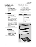
Push the front panel to the desired position.
¾
Make sure that the front panel is in the correct
position.
¾
Push the stops forwards up to the front panel.
¾
Tighten the screws.
Connecting the connection contact for
wall box and window switch (multi-
function contact)
DANGER
Fatal electric shock due to improper
connection.
¾
Only have work on the voltage
supply carried out by a qualified,
trained specialist electrician under
consideration of the country-specific
regulations and standards (in
Germany e.g.
DIN 57100/VDE 0100, Part 701).
¾
Have the following steps carried out by a
specialist electrician only.
A window switch and a berbel wall box (e.g. BMK-F)
can be connected to the device. The cable
terminals for this are mounted on the device's fan
housing.
Connection schematic for the multi-function contact
and the wall box contact
ATTENTION
Damage to the electronics if the
polarity of the control cable is incorrect.
¾
Make sure that the polarity of the
control cable is correct.
¾
Only connect wire 1 to terminal 1
and wire 2 to terminal 2.
7
4
1
5
6
2
3
Terminal for the multi-function contact (F-K)
Terminal for the wall box (BMK)
Control cable
Power supply unit
Wall box BMK-F
Actuation contact, potential-free
Control box for the berbel extractor hood
Connection terminal for the wall box
The connection terminal for the wall box
automatically controls the remotely controlled wall
box BMK.


