background image

Содержание R Type

Страница 1: ...Handbook t rtr Ine BentleyR Type Number XIV Reprinted IWSW Pmduet Support Graphics Ltd 3l7 nt...

Страница 2: ...and include detailed directions for lubrication and maintenance Owners and drivers should therefore familiarise themselves with the first two chaptersin orderto operate the car successfully referring...

Страница 3: ...rnu The Fuel System Fuel Pumps Faulty Operation of Pumps Fuel Tank Fuei Filters Fuel Gauge The Carburetters Action Automatic Air Valve Throttle eontrol Automatic Choke Control Float Feed Mechanisms Fu...

Страница 4: ...tion coil Ignition Timing Firing order of cylinders spark ing __Plugs ltarter Motor starter Motor Switch Micro switch use of starter Motor Electric Fuel Pumps and Gauge Electric Horns De misting Equip...

Страница 5: ...alve Rockers Aerial Operation of Air Silencer and Cleaner Aligning the Headlamps Ammeter gg Anti Freeze Mixtures 2g Er Automatic Air Valve Carburetter 3o 49 Automatic Choke Carburetter 5r 34 65 2E 92...

Страница 6: ...ubrication of Coolant Level in Radiator i 25 Coolant Mixture Coolant Temperature Crankshaft Cut out Automatic Cylinders Firing Order of Dampers Hydraulic Shock Pecn 42 48 52 30 49 52 5o 35 z6 22 73 r7...

Страница 7: ...ilter Cleaning Fuel Firing Order of Cylinders Float Feed Mechanism Carburetter Frost Precautions during 25 Fuel Failure of Supply of Fuel Feed System 23 Fuel Gauge Fuel Pumps Fuel Filters Fuel Tank Fu...

Страница 8: ...ended 27 Lubrication Centralised Ch Lubrication Engine Lubrication Gearbox Lubrication Periodic Lubrication Rear Axle 35 28 3T Lubrication Wheel Bearings Luggage and Spare Wbeel Missing Fire Motor Ser...

Страница 9: ...Driving on Spare Wheel Compartment Spark Gaps Standard Spring Shackles Lubrication of Springs Road Stabiliser Front Starter Motor Starter Motor Bearings Starter Motor Brushes Starter Motor Connections...

Страница 10: ...ometer Coolant Temperature Thermostat Engine Throttle Control Tools Tow Starting Tyre Pressures Tyres Sizes of Tyres Removal Upholstery and Carpets Universal Joints Valves Oil Relief Valve Rockers Val...

Страница 11: ...ver s Controls Radio Crankcase Drain Plug Damper Rear Hydraulic Shock Diagram of Braking System Diagram Electrical Wiring Door Hinges Drain Tap Cylinder Jacket Dynamo Engine Lubrication System Engine...

Страница 12: ...e and Spare Ignition Coil Chassis Engine Wheel Compartment Motor Starter Mounting Rear Wheel Oil Filter Oil Relief Valves Engine Operating Wheel Jack Positioning Rear Wheel Propeller Shaft Pump Chassi...

Страница 13: ...t if no attempt is made to interfere unnecessarilywith adjustments An owner would do well to instruct his driver as follows Lubricate effectively in strict accordancewith the advice given in this book...

Страница 14: ...all times to be called in for consultation on any mattersaffe6tingyour car If therefore you requireany assistance we ask that you shouldimmediatelycontact the special Retailer who will be only too ple...

Страница 15: ...d tappetsare lubricated Two gallon capacity sump Ganburetten Two specialtype S U Air intake silencerand air cleaner Fuel System Eighteen gallontank at rear of chassis Supply by electricpumps Fuel leve...

Страница 16: ...eion Semi elliptic springs in combination with controllable hydraulic shock dampers Fnont Suspension Independent open helicalspringsin combinationwith hydraulic shock dampers Steering Cam and rollerty...

Страница 17: ...5f Ghassisand Engine Numbers The chassisnumber will be found on the identification plate fixed to the front of the dashboardunder the bonnet and alsostampedon the left hand sideframe memberjust in fr...

Страница 18: ...iper switch Turn clockwise first position normal secondposition fast 12 Fuel warning light Steadyglow at 2 3 gallonsreserve 13 Oil level indicator Pressbutton and read on fuel gaugedial 14 Direction i...

Страница 19: ...he gearlever on the steeringcolumn is in neutral quadrant gear position N as it is only in this position that the starter switch is operable Before starting the car in temperaturesaboaefreezingpoint f...

Страница 20: ...the suitable gear ratio according to the degreeof throttle opening and the speedof the car The gearlever quad rant is provided with a gate between positions 2 and 3 andabutton on the lever has to be...

Страница 21: ...ther damage i The car shouldnot be towed if there is any sign of mechanical failure or breakagein the gearbox In this casethe car must be transported ii when satisfied that the gearbox is undamaged re...

Страница 22: ...hangesbetween znd speedrange ahd reverse when shunting are facilitated It should be noted that when starting the car from cold the engine will run at a fast idle with the consequentbuild up of an oper...

Страница 23: ...sthe provisionof an automaticoutput regulator in conjunction with a shunt wound dynamo adjusts the chargerate to suit the state of the battery When the battery is low in charge the arnmeteron the inst...

Страница 24: ...for use on the Bentley car are India Winter Type It is suggestedthat two spare wheels might be fitted with Snow Tyres and held in the garage for change overwith the rear wheels of the car when conditi...

Страница 25: ...ur if the high speedposition is used when the windscreen is nearly dry causinga high resistance to the blademovement When the circuit breaks the wiridscreenwiper will stop but will restart if allowedt...

Страница 26: ...he coolingsystem See page79 If the original coolanthas beenreplacedwith water and the car hasto standdxposed to frost with the enginenot_ running it is of vital importance thal the systemshould be dra...

Страница 27: ...originalfactory adjustments andit is therefore most important that after the car hascompletedthe first r ooomiles running it shouldbe taken to the Bentley Retailerin your territory for the appropriate...

Страница 28: ...iscosity would provide easierstarting and satisfactorylubrication The following oils are recommended Shell X roo eo X roo 3o Vacuum Mobiloil Arctic Mobiloil A Equivalentoils to the aboveare alsomarket...

Страница 29: ...APACITIES U C L oilit Donax A r Mobiloil Arctic Special Pump Stanter Motor Geans Engine Gearbox Rear Axle ChassisOil Pump Cooling System Fuel Tank S A E Spec 70 R 2 pints Imp approx pints I p pints Im...

Страница 30: ...e parts of the system Replenishreservoir as necessary but do not overfill Leave one inch betweenoil level and bottom of filler orifice Reservoiron front of dashboard under bonnet Prnroorc LunnrcerroN...

Страница 31: ...omatic Transmissioh Type A Fluids to the level marked on the dipstick Seepage27 Access removerubber bung in floor in front of front passenger s seat 10 Garburettens Inspect oil level in oil reservoiro...

Страница 32: ...ernorspindle Seepageg2 l 6 Contact Breakers Apply one dropof oil A with oil canto the pivot pin of each rocker orrnr Seepagegz 7 Distributor Gam _ Apply one or two drops of oil B to the cam lubricator...

Страница 33: ...ect greaseby meansof grease guninto lubricator located at centre of each universalioint and also into the lubricator on the sliding joint SeeFig 23 4 Valve Rocker Glear arGogr Check the inlet valve ro...

Страница 34: ...no attention between dd carbonisingperiods of the engine 5 Air Gleaner StandandType Removecleanerelementlrom front end of silencer afterunscrewing the wing nut and taking off end cover Carefully wash...

Страница 35: ...auzefilter on fuel inlet to carburetter float chamber taking care first to seethat the ignition is switched off and fuel pumps are thereforeinoperative S ee page47 4 Fuel Tank Release but do not remov...

Страница 36: ...r is locatedonthe front of the dashboard andsupplies oil underpressure for chassis lubrication Fig 4 CHASSISOIL PUMPAND RESERVOIR l F itTl I A diagram of the complete being colouredred Red discs and t...

Страница 37: ...Page36 DIAGRAM CHASSISLUBRICATION SYSTEM...

Страница 38: ......

Страница 39: ...ns 3 and unscrewingthe cap 4 An aluminium distancewasher the felt strainer pad and a wire ga uze support can then be taken out Whenreplacingthe parts the wire gauzesupportshouldbe refitted in the cap...

Страница 40: ...Page38 DIAGRAM ENGINE LUBRICATION SYSTEM...

Страница 41: ......

Страница 42: ...the System The systemis filled or toppedup by opening the oil filler cap 1 Fig 7 on the inlet rocker cover and pouring in the requiredamount of recommended oil It should be appre ciated that it takes...

Страница 43: ...in oil gallery d sshownin the diagram matic illustration Fig 6 Every 5 ooo miles as directed on page3o the filter element should be discarded and replacedwith a new one It is not practicable to clean...

Страница 44: ...ansfer holes in the crankshaft and then to the cranklins through diagonal ducts drilled in the crankshaft webs and so thiough radial holcs to each crankpin big end bearing these bearings being of a si...

Страница 45: ...r l t J J the cylinder block and head to s L p vatve the centre pedestalof the inlet t frti f ffi lii onn tion valverockershaft whichisdrilled Reiurn from filter longitudinally and alsoradially in the...

Страница 46: ...isterthe approximatequantity of oil in the enginesuqp The gaugeis electricallyconnectedto a float unit fitted into the right handsideof the crankcase sump 2 Fig 10 The reading should be taken when the...

Страница 47: ...one or rnore causes In the first place it should be ascertainedthat there is sufficient oil in the sump by referring to the oil level indicator If this is found to bein order the trouble may be dueto...

Страница 48: ...at the ignition condenser is at fault Two condensers aremountedon the sideof the ignition distributor onebeingcarriedasa spare See Fig 43 page93 In the above circumstances it is recommendedthat the wi...

Страница 49: ...right handsidechassis framememberbelowthe rear floor A pipe is arranged along the right hand side frame member conveyingfuel from the tank to the pumps The pipe is seenat a A filter is provided on th...

Страница 50: ...hepumpswill tick continuouslyand noisily On severe gradients and side slopes thesesymptomsmay occur before the tank is completelyempty dueto surgingof firelin the tank which may uncoverthe suctionpipe...

Страница 51: ...aned every 2o ooo miles as directed on page 34 47 1 Body 2 Cover 3 Cover nut 4 Yoke Fie 12 REARFILTER When refitting the cover care must be taken that the cork washer is sound and properly in position...

Страница 52: ...echamber 3 Hydraulicpiston 4 Soienoid 5 ldle Adiustmentscrew This is effectedby using the manifold depression to levitate a piston or air valve carrying a taperedneedlewhich regulatesthe fuel p ass_ag...

Страница 53: ...pressur e may 6e required to displacet heoil sufficientl5z to allow the engagementof the thread of thebil reservoir cap nut If it is suspectedthat the automatic air valve is not working c orrectly the...

Страница 54: ...it must be particular ly noticed that the location of the valve is determined by a shoulder The valve shouldbepushedinto the piston until this shoulder is just flush with the lower face and the grub...

Страница 55: ...he choke valve in the closedposition On starting the engine the valve is held closeduntil the oil pressurebuilds up to a pre determined value to operate the oil pressureswitch and so releasethe chokev...

Страница 56: ...It shouldnever be necessary to remove any other parts of the carburetterthan thosereferredto in the foregoingpages The jet assemblysecuringnut should not be disturbed as the refitting of this requires...

Страница 57: ...aps arld sealingwashers Air Cleaner and Silencen StandandType A cleaneris provided within the front end of the air silencerto prevent the passageof dust and grit to the engine Fig 15 AlR CLEANER STAND...

Страница 58: ...ng every r ooo miles or more often according to the prevailing conditions the frequency being morereadilydetermined by experience in the territory in which the car is operated As directedon page 3o th...

Страница 59: ...Page55 BLANK PAGE...

Страница 60: ...Tsn R Typr BrNrrBy...

Страница 61: ...aulic master cylinder The servo effect is distributed between the front and rear brakes being added therefore to the direct pedal effect in the case of the rear brakes With the leveragesprovided this...

Страница 62: ...rovided that the trigger is still held This device is particularly useful in preventing accidental releaseof the brakeswhen the car is parked To obtain this action the trigger is not directly connecte...

Страница 63: ...or wear of the brake shoe linings and is the only adjustment provided on the whole system It isimportant to notethat in no circumstances shouldadjustments be attempted at anlr other point for instance...

Страница 64: ...he adjusterscomingto the eird of their travel and will have a solid feel quite distinct flom the resistancefelt when the brake shoesare correctly adjusted Fig 18 FRONT BRAKEADJUSTMENT a 1 Adiusterscre...

Страница 65: ...7 and 17 Fig 17 Oil shouldbe applied to these points every 5 ooo miles as directed on page 3r The ball bearing cams which actuate the servo as describedearlier in this chapter are filled with lubrican...

Страница 66: ...pty but taking carenot to empty it completely 6 Tighten the bleederscrewand transfer drain tube to the other front brake 7 Refill the reservoir and bleed this brake in a similar manner 8 Finally refil...

Страница 67: ...matically the timing beirig controlled by the automatic control unit and is a functior of the vehicle speed and the throttle opening Fluid is inserted into the gearbox by removing the dipstick shown a...

Страница 68: ...lug on the fluid coupling can be reached by remoyitg the lower cover of the betl housing 3 Fig 22 and turning the engine by means of the starter motor until the ptug is at the bottom position The gear...

Страница 69: ...ld be injected by means of the grease guninto all the four lubricators Rear Axle The rear axle is of the semi floating type The final drive is by offset hypoid bevel gears which possess the advantages...

Страница 70: ...artei rf pints of freshoil shouldbeinserted usinga syringe This quantity shouldjust causeoil to overflowfrom the f lling orifice Fie 24 REAR AXLE CASING 1 Filler and level plug 2 Draiir plug 3 Breathe...

Страница 71: ...ation of Tyres Balancing Road Wheels Steering Box and Column The steeringmechanismis of the cam and rollertype and requires no attention beyond inspection of the oil level The cover of the box is prov...

Страница 72: ...axlesare pivoted The upper radius arms are connectedto and operate the special Bentleyshockdamper whicheffectivelydampens excessive springaction The main helicalcoil spring is mounted betweenthe forwa...

Страница 73: ...the latter should be removed the nuts screwedup tightly and new split pins fitted The ball joints of the crossand side steering tubes are lubricated from the centralised chassissystem as illustrated i...

Страница 74: ...e cleaied r ry carefullywith a brushdippedin paraffin in order to avoid thl possibilityof dirt entering thehoiewhenthe plug is removed z 9 ly a recommended oil must beused see pagezB and before insert...

Страница 75: ...ioning of the control As it is of such importance that the shock dampers and also the pump and pipe line should be maintained full of oil evidence of undue leakage should be at once reported to Messrs...

Страница 76: ...el thus causing creaks and rattles Lubrication of Wheel Bearings The wheel bearings are correctly packed with ball bearing grease in the first instance and should need no attention between general ove...

Страница 77: ...car applied the hand brake and removed the rear wheel r Roll the spare wheel under the hub the top of the wheel being inclined outwards then with a foot at the bottom of the wheel lift by the rim on t...

Страница 78: ...33 ENTEREDSTUD AT TOP Replace wheel nuts wheel disc and retaining nut as previously described FITTING AND REMOVING TYRES Inextensiblesteelwiresareincorporatedin the edges of the tyres Therefore do not...

Страница 79: ...refitted Inflation of Tyres The pressuresrecommended for the 6 5o by r6 India tyres are z4lbs sq in r 6gkgltq l Cotd 33 lbs sq in 2 32kgltq cm J Tyre pressures will increase slightly uft t continued...

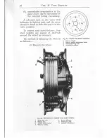
Страница 80: ...sition To correct such out of balance four steel weights are spaced at intervals around the wheel as necessary The method of balancingthe wheel is as follows i Removethe wheel Fig 34 WHEEL BALANCE WEI...

Страница 81: ...performed more easily as the balance weights may then be fitted externally Refit the wheel to the hub Allow to swing and note the tight point Put oneweight here Allow the wheelto swing again If the w...

Страница 82: ...t it 4 holes to one side Fit the 4th weight 4 holes to the other side i If 3 weights are insufficient add the 4th and if this is too much start separatingthe outer z weights asin vi above Removethe wh...

Страница 83: ...opped up with the correct anti freezemixture to maintain the level to the bottom edge of the filling orifice If either of the recommendedcompounds seepage Bz are not available plain preferably soft wa...

Страница 84: ...owever and is effected by releasing the three nuts 9 4 and 5 Fig 37 and moving the dynamo outrvards on the special slotted link The tensionshould be suchthat the fan belt can be moved transversely wit...

Страница 85: ...ply of heat to the induction pipes a ftersta_rting from coldaswell asa rapid warmingup of the enginecoolantjacket Radiator Mounting The radiator comprisestwo main units namely the outer shell andthe m...

Страница 86: ...ost protection ensuredby different strengthsof mixture Freezingpoint Degreesof frost r z F zo F 2 F 300F ro pts ro pts 30 F 35 F r Inhibited z Bluecol Ethvlene Glvcol 6f pts 6f pts rr pts rr pts When...

Страница 87: ...ock through the isolating tap trig 39 to a manually operatedvalve 3 Fig 2 and then to the heater the return being made to the coolant pump The switch mounted on the variable control Fig 39 CAR HEATERI...

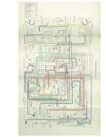
Страница 88: ...Page84 DIAGRAM ELECTRICAL WIRING...

Страница 89: ......

Страница 90: ...relay opeiatedswitch two electrichornswith push buttonswitchat headof steeringcolumn ead side rear and interior lights windscreenwiper trlfficators de froster de mister car heater radio electricfuel p...

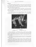
Страница 91: ...onnectionis to the terminal marked F in the fuse box 1 Dynamo Fie 41 THE DYNAMO 3 Slotted Link 2 Cover Brush Gear 4 5 6 and7 Securing Nuts Every 2o ooomiles as directed on page 33 take out the securin...

Страница 92: ...e voltage of a battery varies between certain fixed limits accordingto the state of charge of the battery the voltage being of course a maximum when the battery is fully charged and a minimum when the...

Страница 93: ...output regulatorandcut outrequiresno attention it isasealed unit andnoadjustment of anykind mustbeattempted If anydefects in operationshould develop as describedunder Electrical Fault Localion p g 98...

Страница 94: ...L Parl ing Lights side tail and roof lamps on No reading is shown on the ammeter and all other accessories are off A separateswitch is provided for the ignition marked trOnt and t Off Normally this sw...

Страница 95: ...at the necessary charging shouldbe undertakenby properly equippedservicestation asurilesi the initial charge is correct the battbry will never give satisfactory servtce Topping Up In the majority of c...

Страница 96: ...ng The output of the dynamo on the car is controlled so as to vary with the state of charge of the battery Overcharging the battery is thus automatically avoided The dynamo will under ordinary running...

Страница 97: ...stem instruments or fittings or if the ignition switch be left on in error and the engine happens to come to rest with the low tension contacts in engagement Provision is made for the latter contingen...

Страница 98: ...of the coil The outside of the coil casingshould be kept clean misfiring is occasionallycausedby an accumulationof dirt around the terminals lgnition Timing If the ignition timing hasbeenderanged it c...

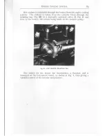
Страница 99: ...ltWick mark on the periphery of the flywheel The contact breaker should now be adjusted by rotating in an anti clockwise direction so that the cam is just on the point of causing the contact break whe...

Страница 100: ...ed The width of the be checked and if necessary resetto o3o 262m m r being the Typ CLN on page3r gapsshould Starten Motor The starter motor is shownin Fig 46 A small planetary reduction gear is arrang...

Страница 101: ...ncontrol lever see Fig 25 Oneswitch is connected in the starter motor circuit 4 Fig 25 and is closedonly whenthe handcontrolleveris ip neutral This en suresthat the enginecanonly be startedup in neutr...

Страница 102: ...e tank unit rheostat andsoarrangedto act in opposition to the control coil The tank unit consistsof a variable rheostat the sliding arms of which are operatedby the up and downmovementof the flbat thu...

Страница 103: ...usingof the mainfuse Fig 42 dueto an earth If the dynamo doesnot charge r Checkcorrectness of ammeterby switchingon headlamps this shouldshowa discharge reading NOTE See that the main switchis in the...

Страница 104: ...atteryin order startermotoris sluggish or doesnot turn examinecommutatorandbrushes Cleanoily brushes andholderswith a rag moistenedwith petrol If motor turns without turning engine check freedomof eng...

Страница 105: ...pping to the right in both headlamps for use in countries where the car is driven on the right hand side of the road r Fit Lucas 3o3or osram oS 5r6R right hand dip double filament prefocus bulbs in bo...

Страница 106: ...otrude through the holes in the flange pressin and twist in a clockwisedirection Fig 47 HEADLAMP CHANGING THE BULB 5 6 7 1 2 3 4 Light unit Bulb holder Bulb Backshell Horizontal adjustment screw Verti...

Страница 107: ...ingthe adjustment of the lamps is to take the caf on a stiaight level stretch of road at night and examine the direction of the beams If one appearsto be out of adjustment adjust as follows Remove the...

Страница 108: ...rning the control fully anti clockwise will switch off the receiver Allow about 40 secondsfor the receiver to warm up after switching on YolumeControl and Oll 0fF Switch TuningPushButtons llanual Tuni...

Страница 109: ...on of one of the Tuning Push buttons between finger and thumb unscrewit about half a turn i e turn it anti clockwise Then push the button firmly as far as it will go Allow it to spring back to normal...

Страница 110: ...rely of pressed steel and possessing greatstrengthandrigidity with minimum weight ensuresthe greateststability of body and chassiscombined with maximum resistanceto accidentaldamage Large doors permit...

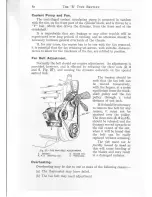
Страница 111: ...on is being depressed other wise there may be insufficient depression to actuate the pump The jets may readily be cleared if thev ever become obstructed with foreign matter by slackening off the knurl...

Страница 112: ...avoided as this invites the collection of water inside the doors which may take some tirne to dry out 4 Use a good wax polish and apply this to a section of the car and polish before proceeding to a...

Страница 113: ...ccasionally check the securing screwsfor tightness and apply sparingly a little greaseto the runnersto ensure smooth operation Upholstery and Garpets In general the leather upholstery has an imperme a...

Страница 114: ...which should receive periodical attention similar to the carpets and the other upholstery Sliding Roof Occasionally inspect the side channels of the roof to make sure that the drain holes are clean L...

Страница 115: ...I I O TnB R Typu Bpxrrrv Fig 56 LUGGAGE BOOT SPARE WHEEL AND TOOL COMPARTMENT...

Страница 116: ...ew times to distribute the oil over the cylinder walls Jack up front of car a jacking pad is provided on the centre of the front suspension support on suitable wooden blocks Do not deflate tyres but c...

Страница 117: ...l to correct level with fresh engine oil z_ Pfime cylinders with engineoil 3 If previouslydrained refill coolingsystemto the correctlevel 4 It gearboxand rear axle havebeenfilled with a pure mineral o...

Страница 118: ...d by the Schoolfor instructional purposes The Course is intended for chauffeurs who are undertaking the care of Bentley products for the first time and also for drivers who have had previous Bentley e...

Страница 119: ...CONVERSION TABLES AND FACTORS KILOMETRES_MILES OR MILES_KILOMETRES...

Страница 120: ...qe 77 249 78 858 8o 467 I 2 3 4 5 6 o 6z137 r 2 4 3 t 864 2 485 3 r o 7 3 728 4 350 4 9 7 r 5 592 6 z r 4 6 8 3 5 7 456 8 o78 8 6gg 9 32r 9 942 ro 563 r r r 8 5 r r 8 o 6 1 2 4 2 7 1 3 o 4 9 13 67o 1...

Страница 121: ...o r49 669 t5t z78 r52 888 r54 497 r56 ro6 r 5 7 7 t 6 r59 325 16o g34 5r 52 53 54 J 56 57 58 59 6o 6r 6z 63 64 65 66 67 68 6g 7o 7r 72 73 74 J 76 77 78 79 8o 8r 8z 83 84 85 86 87 88 89 9o 9r 92 93 94...

Страница 122: ...w CONVERSION TABLES AND T ACTORS LITRES_PINTS OR PINTS LITRES Litres to LJ S Crallonsx 0 Zi4L7...

Страница 123: ...26 t393 z6 7o75 27 2758 27 844o z8 4rz3 r 7598 3 5196 5 2794 7 0392 8 7ggo ro 5588 rz 3t86 r4 o784 r5 8382 t7 5g8o 19 3578 z r 1 1 7 6 22 8774 24 6372 z6 397o 28 1568 29 9166 3t 6764 33 4362 35 196o s...

Страница 124: ...55 r r98 55 688o 56 2563 56 82454 5r 52 53 54 J J 56 58 59 6o 6r 6z 63 64 65 66 67 68 69 7o 7r 72 73 74 76 78 79 8o 8r 8z 83 84 85 86 87 88 89 9o 9r 92 93 94 95 96 97 98 99 IOO 8g 7 gB 9r 5o96 93 269...

Страница 125: ...CONVERSION TABLES AND F ACTORS rirocRAMMEs PERse cENTIMETRE POUNDS PER SQ INCH OR POUNDS PER SQ INCH KILOGRAMMtrS PER SQ CENTIMETRB Kilogrammes to Tons Engtish 1016 05...

Страница 126: ...0 9 3 5 3 r638 3 234r 3 3044 3 3747 3 4450 3 5 r 5 3 I 2 3 4 5 6 7 8 9 I O I I T 2 I 3 r4 r5 r6 r7 r8 r9 20 2 I 2 2 23 24 25 z6 27 z8 29 3o 3r 32 33 34 35 36 37 38 39 40 4t 42 43 44 45 46 47 48 49 5o...

Отзывы: