background image

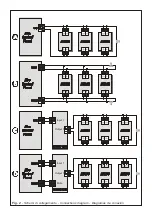
Fig. 2

 - Schemi di collegamento - Connections diagram - Diagramas de conexión


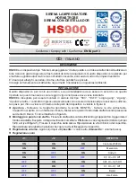
Содержание HS900

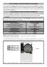
Страница 1: ...di ingresso alla scatola devono essere dimensionati per assicurare sufficien te spazio per i fili La visione d insieme delle parti del dispositivo visibile in figura 4 z Apertura Sollevare la targhet...

Страница 2: ...sincronizzatore SYNC900 In questo caso bene programmare la NAC di centra le FISSA non temporizzata Il sincronizzatore provveder ad attivare i lampeggiatori tutti in modo sincronizzato SYNC900 provvede...

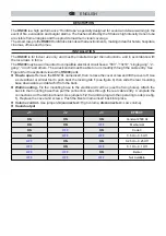
Страница 3: ...and others The wires conduit must be able to run smoothly through the cable entry See Figure 4 for the exploded view of the HS900 parts z How to open Remove the BENTEL name insert then remove the cove...

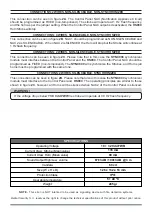
Страница 4: ...hat in this case the SYNC900 synchronizer module must interface between the Control Panel and the HS900 The Control Panel NAC should be programmed as FIXED non temporized The SYNC900 will synchronize...

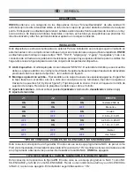
Страница 5: ...a tapa se abrir con un simple movimiento Seguidamente sacar la tapa trasera de la abrazadera presionado dobre el diente de fijaci n 1 tal mostrado en figura 3 z Montaje en pared con estribo Fijar el e...

Страница 6: ...n hay que interponer el m dulo sincronizador SYNC900 entre el panel y el HS900 El funcionamiente de este ejemplo es el mismo que el de la figura 2C pero en este caso si se silencia la salida de panel...

Страница 7: ...Fig 2 Schemi di collegamento Connections diagram Diagramas de conexi n...

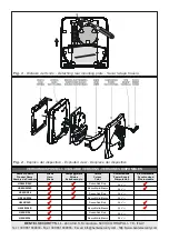
Страница 8: ...dispositivo Fig 3 Distacco del fondo Detaching rear mounting plate Sacar la tapa trasera BENTEL SECURITY S r l Zona Ind S Scolastica 64013 CORROPOLI TE ITALY Tel 39 0861 839060 Fax 39 0861 839065 E m...

Отзывы: