background image


- 8 - 

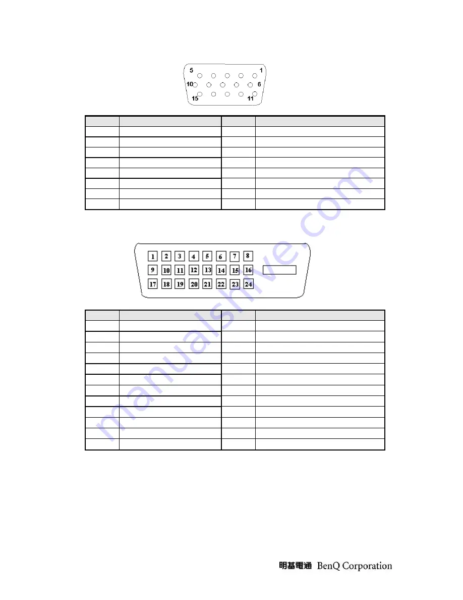
Note-1: 

The pin assignment of 15-pin D-sub connector is as below,  


Pin 

Signal Assignment 

Pin 

Signal Assignment 

Red video 

PC5V (+5 volt power) 

Green video 

10 

Sync Ground 

Blue video 

11 

Ground 

Ground 

12 

SDA 

Cable Detected 

13 

H-Sync (or H+V) 

Red Ground 

14 

V-sync 

Green Ground 

15 

SCL 

Blue Ground 


Note-2: 

The pin assignment of 24-pin DVI-D connector is as below,


Pin 

Signal Assignment 

Pin 

Signal Assignment 

TMDS RX2- 

13 

Floating 

TMDS RX2+ 

14 

+5V Power 

TMDS Ground 

15 

Ground 

Floating 

16 

Hot Plug Detect 

Floating 

17 

TMDS RX0- 

DDC Clock 

18 

TMDS RX0+ 

DDC Data 

19 

TMDS Ground 

Floating 

20 

Floating 

TMDS RX1- 

21 

Floating 

10 

TMDS RX1+ 

22 

TMDS Ground 

11 

TMDS Ground 

23 

TMDS Clock+ 

12 

Floating 

24 

TMDS Clock- 


Содержание GW2760HS

Страница 1: ...2012 12 10 Notice For RO to input specific Legal Requirement in specific NS regarding to responsibility and liability statements Please check BenQ s eSupport web site http esupport benq com to ensure...

Страница 2: ...tance 20 4 Level 1 Cosmetic Appearance Alignment Service 26 4 1 Software Firmware Upgrade Process 26 4 2 DDC EDID Upgrade Process 31 4 3 Alignment procedure for function adjustment 37 5 Level 2 Disass...

Страница 3: ...m diagnostics tests troubleshoot problems and align the BenQ product 1 1 Trademark The following terms are trademarks of BenQ Corporation BenQ Importance Only trained service personnel who are familia...

Страница 4: ...ersons are safe while you are servicing the product DO NOT perform any action that may cause a hazard to the customer or make the product unsafe 3 Use proper safety devices to ensure your personal saf...

Страница 5: ...M270HVN02 0 PS VA LED backlight Screen diagonal 27 597 6 H x336 15 V Display Format 1920 H x 1080 V Panel Display information Pixel Pitch 0 31125 mm x 0 31125 mm per one triad Color Gamut 69 Viewing...

Страница 6: ...dio speakers supported Yes 1Wx2 Audio Jack input connector supported Yes Earphone Jack input connector supported Yes Microphone function supported No Mechanical Tilt base design Yes From 5 to 15 degre...

Страница 7: ...lor Black Length 1500 50 mm 19 pin HDMI Pin assignment 15 pin D sub connector See Note 1 For 15 pin D sub 24 pin DVI D connector See Note 2 For 24 pin DVI D HDMI See Note 3 For 19 pin HDMI Video input...

Страница 8: ...d 14 V sync 7 Green Ground 15 SCL 8 Blue Ground Note 2 The pin assignment of 24 pin DVI D connector is as below Pin Signal Assignment Pin Signal Assignment 1 TMDS RX2 13 Floating 2 TMDS RX2 14 5V Powe...

Страница 9: ...9 Note 3 The pin assignment of 19 pin HDMI connector is as below...

Страница 10: ...nal full scale value Refer to VESA VSIS Standard V1R1 Overshoot Undershoot 12 of step function voltage level over the full voltage range Refer to VESA VSIS Standard V1R1 3 1 1 4 Scan range Item Condit...

Страница 11: ...1280x720 45 00 59 94 74 25 P 1280x720 60 1280x720 44 77 59 86 74 50 P 1280x768 60 1280x768 R 47 40 60 00 68 25 P 1280x800 60 1280x800 49 702 59 81 83 50 P 1280x960 60 1280x960 60 00 60 00 108 00 P 12...

Страница 12: ...ratio 10 R L 178 degrees typ At Contrast ratio 10 U D 178 degrees typ Display colors 16 7 Millions colors RGB 8 bit Color temperature specification Color mode Color temperature x Y Normal 6500k 0 313...

Страница 13: ...tion 1 15G 1 The product should be packaged and non operating 2 The duration of endurance is 30 minutes per axis X Y and Z 3 Procedure Confirmed sample with appearance and function ready before testin...

Страница 14: ...rs min See Note 4 Note 4 Backlight life time is defined as the time when brightness of backlight become 50 or less than its original value at the condition of typical backlight operation current for C...

Страница 15: ...olor Coordinates CIE White White x 0 283 0 313 0 343 White y 0 299 0 329 0 359 Luminance Uniformity 9 points measurement 75 80 White Luminance CCFL 6 0mA center cd m2 240 300 Crosstalk in 60Hz 1 5 60H...

Страница 16: ...0 255 RGB 16 235 HDMI input signal only Display Information For input timing Volume 0 100 Mute On Off Hot key for Picture mode Hot key for Brightness Hot key for Contrast Hot key for Volume 1A1D1H Ho...

Страница 17: ...ABS 94 HB Heat deflection To ABS 65 UV stability ABS Delta E 8 0 Resin MPRII ABS Texture BTN RC MT 11015 Lens Glossy 95 BZL CLMN Base Polish 8000 Color DB59A 3 1 1 22 Carton Item Condition Spec OK N...

Страница 18: ...A 4 Pallet B 4 Pallet A 10 40 1282 WW 1050 JP 1232 EU Pallet A 64 Pallet B 80 Pallet C 70 Pallet A 64 Pallet B 90 Pallet A 50 Pallet A 8 Pallet B 7 Pallet C 3 Pallet A 8 Pallet B 8 Pallet A 21 Without...

Страница 19: ...19 3 1 2 Certification...

Страница 20: ...cified technical esthetic and workmanship requirements leading to an evaluation of the degree of fitness for use including possible personal injury or property damage for the user of the product 3 2 5...

Страница 21: ...immediately upon detection the lot or batch shall be rejected and further shipments shall be held up pending instructions from the responsible person in relevant organization Major Defective 0 4 AQL M...

Страница 22: ...l not arrive in good condition at customer Minor 1 3 Carton damaged 3cm to 6cm dia badly taped or stapled product will arrive in good condition at customer Minor 1 4 Wrong marking of trade mark Major...

Страница 23: ...1 Missing knob or switch not safe Critical 3 23 Missing knob or switch but safe Major 3 24 Poor functional user controls in mechanical Major 3 25 Unreadable printing of user controls label Major 3 26...

Страница 24: ...tern KEY PATTERN TEST ITEM A FULL WHITE H Size V Size Viewing Angle Light Output Impurity Spot check Contrast Ratio Brightness adjust Range E DARK Background Spot check F FULL W R G B Impurity Spot ch...

Страница 25: ...PS Model Name GW2760HS Bright Dot Single 2 Dots Dark Dot Single 5 Dots Density Bright Dot Distance between two Bright Dots 15mm Dark Dot Distance between two Dark Dots 15mm Bright to Dark Dot Distance...

Страница 26: ...nt Step 1 Prepare PC with 2K or XP system printer port cable x1 and D sub cable x1 Step 2 Prepare ISP board and setup jumper as below Pin 1 2 of J5 J6 J7 and J8 are for Firmware Upgrading Please Setup...

Страница 27: ...board Then connect signal cable between ISP board position 1 and monitor 2 Power on the monitor a Connect the Printer Cable to the Printer Connector b Connect the other side to the Board c Connect the...

Страница 28: ...zip Port95nt and install into your computer Step 2 Un zip MStarISPToolv V4 5 105 zip ISP Tool Step 3 Run Program MStarISPToolv V4 5 105 exe refer to below Picture Step 4 Program Setting Click the butt...

Страница 29: ...29 Step 5 Click the button Read to open the firmware that will be ISP Step6 Click the button Connect one cue Device Type is xxxx will show as bellow If not check connects again...

Страница 30: ...30 Step7 Click the button Run to continue the programming If the ISP process is successful it will show Pass Step8 AC off on and turn on Factory Menu and check F W version Step7 Switch Burnin to off...

Страница 31: ...nd install into your computer Step 2 Un zip QEDID302 rar 4 2 2 Hardware configuration Step 1 Prepare PC with 2K or XP system printer port cable x1 and EDID cable x1 as below EDID cable PN 5K 09C09 501...

Страница 32: ...32 Step 3 Connect printer port cable between PC LPT1 and ISP board then connect EDID cable between ISP board position 1 and monitor Connection...

Страница 33: ...off first then turn Burn in ON b If burn in is off please turn burn in ON Note2 If you don t enter factory mode to turn burn in ON VGA EDID and Serial Number writing will be failed Note3 The above st...

Страница 34: ...34 Step 2 Click Open File and select VGA DVI or HDMI EDID file If load file is successful it shows Open EDID Table OK...

Страница 35: ...35 Step 3 Click on Option and choose User Factory Mode to enter factory mode Step 4 Modify Serial Number and click S N RUN button to update EDID and serial number to EEPROM...

Страница 36: ...Step 5 If write EDID and serial number is successful it shows Write EEPROM OK And then click Read EDID button to check if successful or not Step 6 After updating EDID press ClearUser to exit factory m...

Страница 37: ...gs to following values Contrast 50 Brightness 100 Color temp User Mode Picture mode User Language English Burn In ON Then turn off the monitor power 3 Turn on power enter user area C Color balance adj...

Страница 38: ...29 0 020 Min 180cd m2 Bluish 9300k 0 283 0 020 0 297 0 020 Min 160 cd m2 Reddish 5800k 0 326 0 020 0 342 0 020 Min 180 cd m2 User Mode Panel default color temp Min 200 cd m2 sRGB 6500k Gamma 2 2 0 2 0...

Страница 39: ...tep1 prepare PWR_BD IF_BD and fix on SHD Step 2 prepare Mylar 4K 1Y401 001 on SHD Step 3 Fix HDMI and IO by screw Step 4 Put panel on Bezel Step 5 Connect LVDS Step 6 Put Shielding on the Panel and As...

Страница 40: ...40 Step 7 Plug panel connectors and manage the wire by tape Step 8 Assembly the CTRL_BD on RC Step 9 Assembly the rear cover bezel and fix the BKT_HINGE by screw Step 10 Assembly the stand...

Страница 41: ...bly Assembly Circuit Board and Standard Parts Replacement 5 1 Exploded View This Service BOM is subject to change Please check it on eSupport and SPO system before service parts order release 1 2 3 4...

Страница 42: ...position that the monitors be placed and the quantity of the monitor prepare the area for material flow according to the actual condition plan the disassemble layout 4 Prepare the implement equipment...

Страница 43: ...43 1 Disassembly the bezel from the monitor notice the disassembly order 1 Top 1 parts of bezel 2 Left 2 parts of bezel 3 Right 3 parts of bezel 4 Bottom 4 parts of bezel...

Страница 44: ...44 2 1 Turn over the monitor dismantle the Rear cover from the monitor 2 Tear down control board and take out the wires 3 Tear down Conductive tape...

Страница 45: ...45 4 Remove the LAMP wire FFC cable...

Страница 46: ...46 5 Unlock the 5pcs screw Take the main SHD off the BZL then take the panel off the BZL 6 1 Take the Mylar off the BKT 2 Unlock the 7 screws...

Страница 47: ...47 7 Disassembled the PCBA from the Main SHD Disassembled the I F and the Power Board then take out the 2 wires 8 Tear down SPK from SHD The assembly is in the reverse order of disassembly...

Страница 48: ...48 5 3 Packing...

Страница 49: ...trol the adjustable items and get some information about this monitor and the best function is to offer users an easy method to set all adjustable items well just by pressing OSD auto adjust function...

Страница 50: ...50 5 5 Trouble Shooting Guide 5 5 1 No Display or display is unstable on analog or digital port 5 5 1 1 Interface Board...

Страница 51: ...51 5 5 2 BUTTON Function 5 5 2 1 OSD Function...

Страница 52: ...1 R615 No Reaplce IC601 Yes 5V ok Yes Check CN701 pin2 BL ON is Hi Yes Check CN701 pin1 BRT ADJ exist Yes Check I F BD Yes Replace IC851 No Yes Replace Q821 D821 No Check Panel Yes No No Check D701 D7...

Страница 53: ...dule MCU stores source code and offers H W DDC2Bi function controls system processing EEPROM is stored DDC data OSD common data and user mode data b IC introduction 1 DDC Display Data Channel function...

Страница 54: ...tor 2 Menu key to enter sub menus or select items 3 Up Right key to select previous and to increase adjustment and Audio submenu hotkey 4 Down Left key to select next and to decrease adjustment and Di...

Страница 55: ...2 001 Metal Metal to metal Plastic to metal 9 0 1 0 M4 0 7 2 6 8F 00273 6R0 SCRW TAP PH F 10WSH M3 6L C ZN Metal Metal to metal Plastic to metal PCB to metal None tread 8 10 Have tread 6 8 Aluminum 4...

Страница 56: ...R0 SCRW TAP FPHM3 5 B ZN Metal Metal to Plastic 6 8 M3 0 5P 1 21 8F 5A456 7R0 SCRW MACH FLAT M4 7L B ZN NYL Metal Metal to Metal Plastic to Metal 8 10 M4 0 7P 2 22 8F XA326 150 SCRW TAP FLAT M4 15L B...

Страница 57: ...o metal Plastic to metal Metal to plastic Plastic to plastic Metal None tread 8 10 Have tread 6 8 Plastic 5 0 1 0 Metal 2 68 0 03 Plastic 2 35 0 05 2 2 8F 5A356 100 SCRW MACH FH M4 10L B ZN NYL Metal...

Страница 58: ...58 Appendix 2 Physical Dimension Front View and Side view Fig 1 Physical Dimension Front View and Side view...

Страница 59: ...59 Fig 2 Appearance Description...

Отзывы: