


64
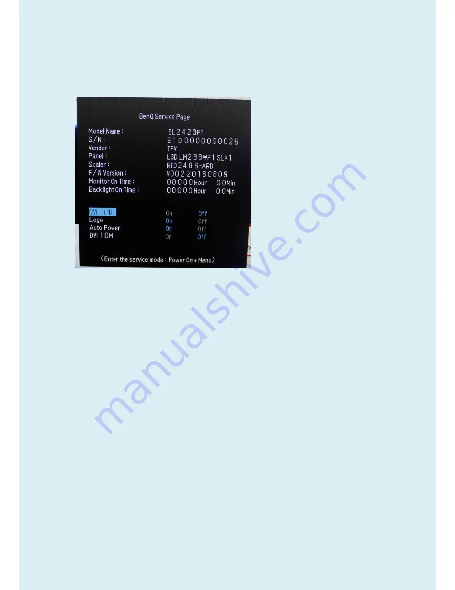
Factory OSD Menu
The service page needs to include that information.
Model name, S/N, Vender, panel, scalar, F/W version, Monitor on time, Backlight on time.
OSD picture is as below
1.
Trigger method: Press “Menu” key and Power on.
2. Press the Menu key will display the service page
3. Press menu key will close the service page.
4. power off will quit the service mode
5. At the service mode, the key function is same as normal OSD define.
6.
The timer can only reset at the service mode by “Timer Reset” (Timer Reset moves to SI factory Area). And
needs to have a warning message to double confirm the reset function. The timer should record up to 99999
hours and will be reset once launch.
7. Add three selected items for HPD(HDMI HPD, DP HPD, DVI HPD) at Service menu
HDMI HPD: To disable the hot plug pin detection.(HDMI port default: Off)
DP HPD: To disable the hot plug pin detection.(DP port default: Off)
DVI HPD: To disable the hot plug pin detection.(DVI port default: Off)
8. A
dd BenQ logo on/off item, the default is “on”
9. A
dd the auto power on item, the default is “on”
10. Add the timer reset warning message, when select the timer reset item, then the warning message will display
and need to confirm it again and the default is “No”.
11. Panel type define need to have the panel version
12. F/W version need to define the dual or analog model
13. Add support
“10m DVI / HDMI” items. (default: Off)
Содержание BL2423PT
Страница 18: ...18 5 2 Panel Inspection Specification ...
Страница 19: ...19 ...
Страница 20: ...20 ...
Страница 21: ...21 ...
Страница 22: ...22 ...
Страница 23: ...23 ...
Страница 24: ...24 ...
Страница 25: ...25 ...
Страница 28: ...28 ...
Страница 30: ...30 4 2 Choose the FTDIUSB communication way 4 3 Click ISP and ISP Option to set the parameter ...
Страница 31: ...31 4 4 Close the ISP Option window and click the BigBin to load the correct F W 4 5 Click to start programming ...
Страница 38: ...38 5 2 Select the EDID folder 5 3 Load EDID successful ...
Страница 39: ...39 5 4 Tick the Only connect VGA and Debug Imformayion 5 5 type in the date and the 13 digit S N ...
Страница 41: ...41 Adjustment Alignment Procedure The Control Panel ...
Страница 43: ...43 ...
Страница 45: ...45 ...
Страница 47: ...47 ...
Страница 49: ...49 ...
Страница 50: ...50 ...
Страница 51: ...51 ...
Страница 54: ...54 ...
Страница 55: ...55 ...
Страница 57: ...57 ...
Страница 59: ...59 ...
Страница 67: ...67 Six Angles View ...
Страница 74: ...74 9 Unscrew the screws and remove the cover to remove the key board and daughter board from bezel ...
Страница 77: ...77 5 Assemble the panel on the bezel ...


