background image

58 

Mounting installation  

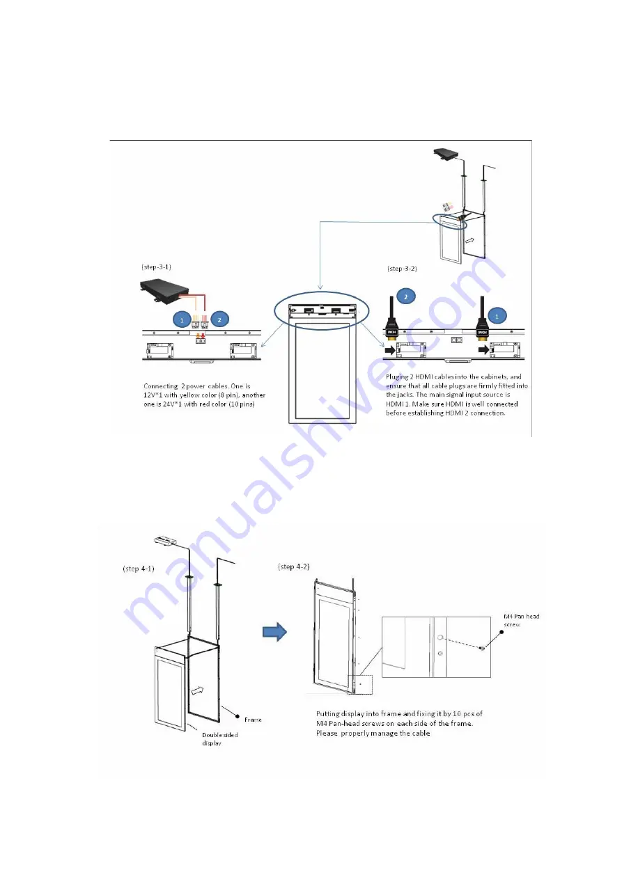
Step 3: Connecting the Power cables & HDMI cable with double sided panel

1.  Connecting the Power cables
2.  Connecting the HDMI cables
3.  Screwing the downside cover back

Step 4: Fixing the double sided display with Frame

1.  Putting the double sided display into the Frame
2.  Then, fixing them by screws

Содержание 9H.F67PK.NA6

Страница 1: ...Digital Signage IFP Installation Handbook ...

Страница 2: ...erwise without the prior written permission of BenQ Corporation Disclaimer BenQ Corporation makes no representations or warranties either expressed or implied with respect to the contents hereof and specifically disclaims any warranties merchantability or fitness for any particular purpose Further BenQ Corporation reserves the right to revise this publication and to make changes from time to time ...

Страница 3: ...1 PH5502 40 Tiling PL490 PL552 PL553 PH5501 PH5502 44 Operating Instructions of Edge Alignment Kit Pin PL4901 PL5501 PL5502 45 Tiling PL4901 PL5501 PL5502 46 Special signage installation guide 48 D series Full HD 55 inch dual side display 48 Mounting installation 51 Ceiling Mount 51 Notice 54 U Mount 56 H mount 60 Digital Signage Bar Type Series 61 Installation notice 61 Adjusting the OSD setting ...

Страница 4: ...mer feedback form customer information and description of problem 87 Part II problem resolving attempt troubleshooting 89 Pictures for reference 94 Appendix 3 Basic Troubleshooting Checklists for Video Wall 90 Part I customer feedback form customer information and description of problem 90 Part II problem resolving attempt troubleshooting 92 Appendix 4 Basic Troubleshooting Checklists for X Sign 9...

Страница 5: ...l Display LCD panel of the display has a very thin protective layer of glass which is liable to marking or scratching and cracking if struck or pressured Please protect the display with cushions during installation Move a display by holding the handles on the back of the display Do not touch the LCD panel directly to avoid possible scratches Do not move a display by holding its frames To maintain ...

Страница 6: ...n you want to place the display face down prepare a flat and horizontal surface that is larger than the display and spread a thick protective sheet on it Be careful not to scratch any parts of the display when upturning the display Lift the display up horizontally by holding the four 4 handles Do not lift the display against its corner 90 90 ...

Страница 7: ...ly may cause injuries and damages to the personnels and the display itself Be sure to use the alignment screw s to set the vertical alignment when installing the display Leave some space in advance when installing the display Use the alignment screw s on the bracket to reduce the gap between the display to avoid collision It is recommended to use the bracket which can be adjusted vertically and ho...

Страница 8: ...he unit completely leaving some opening for heat dissipation to minimize the effect of foreign air particles Notes on using the remote control Point and aim the top front of the remote control directly at the display s remote control sensor window when you press the buttons Do not let the remote control become wet or place it in humid environments like bathrooms When using the remote control confi...

Страница 9: ...20 mm when placing two monitors side by side Use an IR extender cable 3 5 mm cable to avoid interference between IR remote controller and the Touch Screen when placing multiple displays side by side The remote control may not function properly when the remote control sensor on the display is under direct sunlight or strong illumination or when there is an obstacle in the path of signal transmissio...

Страница 10: ...mance Pay attention to the following notes when you connect cables Turn off all devices before making connections Use certified high quality cables and signal amplifiers repeaters Familiarize yourself with the ports and sockets on the display and the devices you want to connect Be aware that incorrect connections may adversely affect picture quality Do not remove cables from the ports and sockets ...

Страница 11: ... repeater using a D Sub 15 pin cable 2 Connect the VGA output jack on the computer to the VGA input jack on the VGA signal amplifier repeater using a D Sub 15 pin cable 3 Connect the computer s audio output jack to the audio input jack on the display using a suitable audio cable D Sub 15 pin cable Audio cable Computer D Sub 15 pin cable VGA signal amplifier repeater Display Audio input jack VGA in...

Страница 12: ...meters deployment of an HDMI signal amplifier is highly recommended 1 Connect the HDMI input jack on the display to the HDMI output jack on the HDMI signal amplifier repeater 2 Connect the HDMI input jack on the HDMI signal amplifier repeater to the HDMI output jack on the HDMI source device using an HDMI cable Refer to the User Manual of your display for the location of HDMI input jacks The HDMI ...

Страница 13: ...e User Manual of your display for the location of USB port Any cable used in prior installations for other displays and projectors in the same location should not be used for a new installation of the display Use only a high quality faceplate The total cable length between the display computer and faceplate should not exceed 5 meters If you need to extend the length of USB connection refer to Exte...

Страница 14: ... commercially available active powered USB CAT converter extender on the market to extend the length of USB connection over a Category 5 5e 6 network cable 1 Connect the mini B plug of the supplied USB cable to the USB Mini B port on the display and the type A plug of the cable to the USB type A port on the active USB CAT converter 2 Connect a Category 5 5e 6 network cable to the RJ 45 LAN ports o...

Страница 15: ...ion cable 2 Connect the type A plug of the active USB extension cable to the USB port on the faceplate Refer to the User Manual of your display for the location of USB port Refer to the documentation of the active USB CAT5 converter for the maximum length of the Category 5 5e 6 network cable The type of USB port and plug on the active USB CAT converter may be different from the description above U...

Страница 16: ... 5e 6 network cable to the RJ 45 LAN port on the converter 3 Connect the converter to the faceplate using a suitable USB cable Refer to the User Manual of your display for the location of USB port For best results use only a certified active USB extension cable and high quality faceplate The type of USB port and plug on the active USB extension cable may be different from the description above Use...

Страница 17: ...ion above Use a USB cable that matches the USB jack on the display and the USB port on the active USB CAT converter Keep the Category 5 5e 6 network cable away from power lines and cables to avoid electronic interference The total length of the USB cables used to connect the display to the active USB CAT converter converter to the faceplate and computer to the faceplate should not exceed 5 meters ...

Страница 18: ...is on top of all other slave devices called Function A computer is the most common USB host Any device that has a USB host controller and related hardware and software installed can also become a USB host A USB function can be a USB mouse keyboard or storage device A maximum of 7 tiers including the root tier are allowed in a single USB network Note that a USB device that performs both as a hub an...

Страница 19: ...urrently defined in the USB 2 0 specification Low speed data transmission at 1 5Mbps Full speed data transmission at 12Mbps High speed data transmission at 480Mbps The actual transmission speed is determined by the device with the lower or lowest speed For example if a low speed 1 5Mbps USB peripheral is connected to a high speed 480Mbps USB host the maximum transmission speed between these device...

Страница 20: ...d as they may not work in all instances For example passive extension cable assembly a cable that has a Type A plug on one end and a Type A receptacle on the other or a Type B plug on one end and a Type B receptacle on the other This allows multiple cable segments to be connected together possibly exceeding the maximum permissible cable length ...

Страница 21: ... ventilation and heat dissipation keep at least 60 mm of clear space from the mounted displays to the wall Ensure enough gap between displays to protect your LCD screens from the damage through the direct transfer of weight See Checking the safe distance between displays on page 23 for details Notes on moving the display The display has limited mechanical strength To prevent the display from perfo...

Страница 22: ...the gap between displays as instructed in Step 4 5 in Checking the safe distance between displays on page 23 6 To maintain proper ventilation and heat dissipation keep at least 60mm of clear space from the mounted displays to the wall Landscape mode Portrait mode Rotate each display 90 degrees clockwise to install the video wall in portrait mode 60mm 1 52 Various mounting brackets may be available...

Страница 23: ...ed minimum values 5 4mm for PH460 PL460 3 5mm for PL490 PL550 PL552 PH5501 PL4901 PL5501 1 8 mm for PL553 PH5502 0 88mm for PL5502 due to different tiling methods You are provided with gap inspection pads to ensure appropriate space between the cascaded displays during video wall installation Model name Recommended gap between displays P Series 0 5 mm 1 Get one of the provided gap inspection pads ...

Страница 24: ... inspection pad smoothly If the pad is trapped adjust the screws to release more space 5 Insert the pad again and swipe the pad horizontally and vertically between the gap to ensure it can move smoothly Ignore the black tapes on the edge if they stop you Refer to Recommended gap between displays on page 23 for the minimum distance required for each model ...

Страница 25: ...our edge finishing kit you will find the following components Installation For standalone unit Cosmetic Plates Top A Bottom B Left C Right D Flat Enclosure E Corner Enclosure F M3 x 5 mm Screw G M4 x 6 mm Screw H 1 Mount the cosmetic plates in their respective places on the edge of your display and screw in to place using the 6mm M4 screws 2 On each corner mount a corner enclosure piece and fasten...

Страница 26: ...e pieces are fitted to the respective positions i e bottom to bottom etc 1 Mount the cosmetic plates in their respec tive places on the edge of your display and screw in to place using the 6mm M4 screws 2 On each corner mount a corner enclosure piece and fasten each one with 4 of the 5mm M3 screws Where the displays meet use a flat enclosure piece and fasten each of these too with 4 of the 5mm M3 ...

Страница 27: ...y chained displays on page 30 for more information 1 Install the video wall Follow the instructions in Video wall installation guide on page 21 2 Connect the video source e g computer and loop all displays using the required cables See Cable connections on page 28 and Cable extension guide on page 10 for more information 3 Set the horizontal and vertical position of the display wall matrix This he...

Страница 28: ... 3 to connect all displays Refer to the user manual of the purchased model for the location of all input and output ports 5 Decide the way to manage all the daisy chained displays See Managing the daisy chain PL460 PH460 PL550 PH550 on page 35 for more information 6 Change the display settings to optimize video wall performance as suggested See Optimizing the video wall performance and management ...

Страница 29: ...hat are not supplied with your product you can purchase them separately Function Cables required for each display Reference Video signal transmission D Sub Composite cable for analog signals DVI HDMI DP cable for digital signals D Sub Composite and DVI support daisy chaining If the video output is HDMI you can use an adapter to convert the signal into either DVI or Composite before making the dais...

Страница 30: ... Recommended number of display Maximum number of display without a signal splitter DVI I Analog 4 9 DVI I Digital signal 16 25 DP PL PH series 9 SL series 16 PL PH series 12 SL series 25 If connection of more than the maximum number is required use appropriate signal splitters to ensure stable signal transmission and you can loop up to 100 displays for PL460 PH460 PH550 and 225 displays for PL490 ...

Страница 31: ...dently Once the position is set the video source e g computer identifies the number of connected displays and transfer part of the picture to each display accordingly The video wall then outputs one picture as a whole If you prefer to show different pictures on the displays of the video wall you will need to have independent video source for each display Video sources Though the video sources vary...

Страница 32: ...tion on each display to set the position The position is defined by the X Y matrix Starting from the top left of the video wall the number increases as it goes down or goes to the right Different video wall layouts and display position setup Set the display position carefully according to the video wall layout to ensure correct picture output Following are some examples for your reference H 1 V 1 ...

Страница 33: ...ted models only on page 35 for more information 4 Go to Screen Display Wall H Monitors and V Monitors on each display to set the total number of displays counted vertically and horizontally 5 Go to Screen Display Wall H Position and V Position on each display to set the position The position is defined by the X Y matrix Starting from the top left of the video wall the number increases as it goes d...

Страница 34: ...e ID number for different displays as the commands for video wall management would not be received correctly Set the ID number starting from 1 to 98 depending on the number of displays daisy chained There is no specific direction while going through all displays setting up the ID numbers Following are some examples for your reference 1 2 4 3 1 2 3 4 1 2 3 4 1 2 3 4 5 6 7 8 9 To set the ID number o...

Страница 35: ...Connect the supplied IR extender to the IR IN at the back of the first display 3 Aim the supplied remote control at the IR extender just connected within the motion range 4 Go to Setting Advanced IR Out on each of the displays to create an IR loop Now you are ready to control all displays using the remote control Refer to the user manual of the purchased model for the operation of remote control 5...

Страница 36: ...etting each display Select RS 232C 5 Refer to the RS 232 protocol document downloaded from the BenQ local website for the commands Management by LAN PL460 PH460 PL550 PH550 1 Connect the computer to a LAN switch or hub using a RJ45 cable purchased separately if not supplied 2 Connect all displays separately to the same LAN switch or hub just connected with your computer using RJ45 cables purchased...

Страница 37: ...ay Select LAN Refer to the user manual of the purchased model for the detailed settings and the operation of LAN control LAN switch or hub RJ45 cable For PL490 PL552 PL553 PH5501 PH5502 there is no need to select LAN as it is automatically enabled once the device is connected ...

Страница 38: ...s Software Description Multi Display Administrator MDA A software program that enables remote and centralized management of a single or multiple BenQ digital signage displays on a host computer You can create and edit display groups view status of displays as well as change display settings Use an appropriate RS 232C cable Refer to the user manual or BenQ service for more information Contact the B...

Страница 39: ...PL550 PH550 EODIS3 OEM PL490 PL552 PL553 SL490 SL550 PH5501 PH5502 PL5502 PL4901 PL5501 EODIS3 DCOE Software Version PL490 PL552 PL553 PH5501 PH5502 PL5502 PL4901 PL5501 v P 1 0 1 SL490 SL550 v S 1 0 1 Software Description PL490 PL552 PL553 SL490 SL550 PH5501 PH5502 PL5502 PL4901 PL5501 ...

Страница 40: ...of Edge Alignment Kit Pin PL490 PL552 PL553 PH5501 PH5502 Basic composition per set 1 Edge Alignment Kit 1 1PCS 2 Edge Alignment Kit 2 2PCS 3 Thumb Screw 8PCS 4 Edge Alignment Pin 2PCS Edge Alignment Kit 1 Edge Alignment Kit 2 Edge Alignment Pin Thumb Screw ...

Страница 41: ...place at the same plane and uniform gap Installing Edge Alignment Kit Before install edge alignment kit displays must be mounted to video wall frame correctly Using Thumb Screw for easy installing Using Edge Alignment Kit 1 on adjacent four displays Without using edge alignment kit pin ...

Страница 42: ...ion Outer loop Big screw holes for M6 screw Inner loop Small screw holes for M4 screw Remark M6 screw for PL552 PL553 PH5501 PH5502 M4 screw for PL490 2 1 There are two loops of screw holes outer inner depend on the design of each model Please check the user manual for using loop information Outer loop Big screw holes for M6 screw Inner loop Small screw holes for M4 screw 2 Remark M6 screw for PL5...

Страница 43: ... Edge Alignment Pin to secure the flatness of adjacent displays Don t let edge alignment pin to touch the side surface of panel panel will damage due to incorrect installation Using Edge Alignment Pin on adjacent displays There are 8 holes on the four corners of displays designed for plug in the edge alignment pin ...

Страница 44: ... monitors V monitors Position and Frame comp H monitors Adjust displays on the horizontal side V monitors Adjust displays on the vertical side Position Adjust the position of this display in the screen matrix Example 2 x 2 screen matrix 4 displays H monitors 2 displays V monitors 2 displays Example 5 x 5 screen matrix 25 displays H monitors 5 displays V monitors 5 displays Frame comp Choose to tur...

Страница 45: ... best effort but still requires slight adjustment that said to install alignment kit when the adjacent display within less than 0 5mm pitch is advised Installed with caution and with advice by experienced installer is required forcing the display to align by the kit when the display is not properly installed will damage the display as the display might be bended and can cause damage to the panel ...

Страница 46: ...ll Enable disable the video wall mode On switch display content to its corresponding position in video wall Off switch to single display Bezel compensation Select ON to initiate compensation Panel settings Change power on logo procedure 1 Save the picture to the USB root folder The resolution must be 1920 x 1080 and the file must be under100 KB 2 Insert the USB then click Custom logo Scene setting...

Страница 47: ...e display position for special video wall layout If a special layout is requested you will need an additional software and device purchased separately for advanced settings Refer to the user manual of the purchased software for more information ...

Страница 48: ...he barcode is near the front side To make the input source work the front side should always be connected FIRST before the back side Playing the display 1 Always set the front side the display 1 and the back side the display 2 2 There are two ports for media players Try the other side of the display if the player doesn t start 3 When using a computer set the display to extension mode 4 You need tw...

Страница 49: ...cabinet and ensure that all cable plugs are firmly fitted into the jacks The main signal input source is HDMI 1 Make sure HDMI 1 is well connected before connecting HDMI 2 Connecting the power cord Plug in the power cable and turn on the AC power switch HDMI HDMI Back side Front side Power box AC in switch ...

Страница 50: ...50 Special signage installation guide Connecting the cables If the display doesn t work unplug and re plug the cables Make sure the cables are plug in HORIZONTALLY and COMPLETELY ...

Страница 51: ... ceiling with power drill Please select expansion screws according to types of the ceiling The expansion screws B come with your product are designed for cement wall only Screws for wood ceiling installation shall feature adequate strength and validated by qualified technicians 3 Hammer the expansion screws M8xL60 B in the holes drilled earlier and tighten their nuts Power drill Drill head Hammer ...

Страница 52: ...racket Secure the display frame E to the display with the included flat head screws M4xL10 D by a Phillips screwdriver Secure device box to the bracket 1 Remove flat head screws M3xL8 C with a Phillips screwdriver before removing the front cover of the device box F 2 Secure the display box F to the display with the included flat head screws M3xL8 C by a Phillips screwdriver Places washers in seque...

Страница 53: ...e later with the included flat head screws M3xL8 C by a Phillips screwdriver Adjust cable length 1 Leave appropriate cable length by winding the excessive section around the cable slot 2 Replace the plastic covers to the left and right of the bracket before securing them with the included flat head screws M3xL8 C by a Phillips screwdriver ...

Страница 54: ...play 1 and the back side the display 2 2 When using a computer set the display to extension mode 3 You need two different player software to have both sides of the display work at the same time e g Windows Media Player and RealOne Player Each side needs a different player 4 Due to the size and weight of this display it is recommended to move it with at least two persons 5 Power function of the rem...

Страница 55: ... before the mains plug is connected to the mains And when disconnecting the earthing connection be sure to disconnect after pulling out the mains plug from the mains 10 Unplug the display if you are not going to use it for an extensive period of time 11 Unplug the display if you need to clean it with a slightly damp cloth The screen may be wiped with a dry cloth when the power is off However never...

Страница 56: ...e wall The expansion screws B that come with your product are designed for cement walls only Screws for wood wall installation shall feature adequate strength and be validated by qualified technicians 3 Hammer the expansion screws M8xL60 B in the holes drilled earlier and tighten their nuts Power drill Drill head Hammer Phillips screwdriver Pencil DO NOT secure the bracket to any decorative post o...

Страница 57: ...lding two power cables and also 2 HDMI cables 2 Threading the HDMI Power cables through 2 Pipe TOPs mark blue 3 Threading the cables through the frame mark orange Step 2 Set up the display for installation 1 Putting the display front side up 2 Removing I O covers at the sides 3 Removing the downside cover ...

Страница 58: ...s HDMI cable with double sided panel 1 Connecting the Power cables 2 Connecting the HDMI cables 3 Screwing the downside cover back Step 4 Fixing the double sided display with Frame 1 Putting the double sided display into the Frame 2 Then fixing them by screws ...

Страница 59: ...h Bracket L and Bracket corner on the frame at four corners 1 Installing Bracket L 2 Installing Bracket corner 3 Repeating the same actions at four corners Step 6 Assemble Pipe TOP and Pipe BOT 1 Assemble Pipe TOP and Pipe BOT 2 Fix 4 Cover plates ...

Страница 60: ...tallation steps 1 5 of H mount please refer to U Mount on page 56 For steps 6 7 of H mount please read the following Step 6 Assemble Pipe TOP and Pipe BOT 1 Assemble Pipe TOP and Pipe BOT 2 Fix 4 Cover plates Step 7 Mounting Pipe TOP and Pipe BOT with ceiling and ground ...

Страница 61: ...1920x1080 You can make the following display effects by adjusting the OSD setting Model Native Resolution pixels BH2401 BH2401T 1920 x 190 BH3501 BH3501T 1920 x 130 BH280 BH281 BH2801 BH2801N 1920 x 360 BH380 1920 x 545 BH3801 BH3801N BH3801D 1920 x 600 Position Description Top The window is positioned to the top 1 3 of the screen Bottom The window is positioned to the bottom 1 3 of the screen Mid...

Страница 62: ...rresponding resolution 1920 x 600 1 In Windows Setting Display Advanced display setting select the BH3801 and choose 1920 x 600 as resolution setting 2 On BH3801 users can either choose Full or 1 1 in Display Zoom mode If the 1920 x 600 content is not allocated at the right ratio it is caused by frequently switching between resolutions and the setting in the video graphics card goes wrong 1 Please...

Страница 63: ...od 2 Content is in the upper section of 1920 x 1080 1 In Windows Setting Display Advanced display setting select the BH3801 and choose 1920 x 1080 as resolution setting 2 On BH3801 choose 1 1 in Display Zoom mode to correctly display the content 3 To proceed further Windows control choose Full in Display Zoom mode to gain full screen access on BH3801 ...

Страница 64: ...64 Digital Signage Rotation Portrait Guide Digital Signage Rotation Portrait Guide Model X Sign Android Correct Heat Dissipation ST4302 ST5502 SL4302K SL5502K SL6502K SL7502K SL8502K IR Sensor Location ...

Страница 65: ...ility and layout of all ports may vary by model How to connect a DVD player to the display You can use either Component or S Video for connection DVI OUT DVI IN HDMI 2 HDMI 1 VGA OUT VGA IN Audio cable DVD player VCR Component video cable DVI OUT DVI IN HDMI 2 HDMI 1 VGA OUT VGA IN Audio cable DVD player VCR AV cable S Video cable ...

Страница 66: ...mputer to the display through D Sub VGA DVI HDMI VGA as desired DVI OUT DVI IN HDMI 2 HDMI 1 VGA OUT VGA IN D Sub 15 pin cable Audio cable Computer Analog signal DVI OUT DVI IN HDMI 2 HDMI 1 VGA OUT VGA IN Audio cable Computer DVI D cable HDMI cable DisplayPort cable Digital signal ...

Страница 67: ...external speakers While the display is turned off connect external speakers to the SPEAKERS R L jacks on the display via an appropriate audio cable And then turn on the display DVI OUT DVI IN HDMI 2 HDMI 1 VGA OUT VGA IN External speakers ...

Страница 68: ...k if the OSD menu could be displayed If yes the problem lies somewhere else Try with another display resolution or another graphic card GPU Restore the display to the default factory settings The main board could be damaged Contact the BenQ authorized service partner for replacement Screen interference is observed or noise is heard Possible causes Possible solutions This could be caused by other a...

Страница 69: ...geometry and time frequency parameters Refer to the user manual for more information on the menu options Note the picture may be distorted or stretched if fitted to the screen You are running the display at its native resolution but the image is still distorted Possible causes Possible solutions Images from different input sources may appear distorted or stretched on the display running at its nat...

Страница 70: ...y of PIP function also depends on the video sources Refer to Supported PAP input signal combination in the user manual of the purchased model for details The PIP function will be disabled if the video wall or the touch function is in use The picture is not displayed in the center of the screen when the input source is D Sub VGA Go to Screen Adjust Screen to make adjustment For advanced setting cha...

Страница 71: ...vice Either the display s or PC s Speaker has been muted Disable mute by pressing the MUTE button on the remote control The main board could be damaged Contact the BenQ authorized service partner for replacement If the signal source is HDMI DP The Speakers in your OS is not set properly Set DisplayPort or HDMI as the default speaker in your operating system and launch the media player again Your d...

Страница 72: ...infrared plastic filter periodically It is suggested using a small amount of alcohol to clean the infrared plastic filter 3 Moisten a clean soft lint free cloth with a neutral detergent and then clean the touch screen Use a neutral detergent to clean the touch screen Avoid using detergents with erosive substance such as banana oil or ammonia To avoid damage to the screen never use any type of abra...

Страница 73: ...ulti touch 1 0mm over 90 of touchable area RM5501K RM6501K RM7501K RM8601K IST X 2mm for single touch 5mm for multi touch 1 0mm over 90 of touchable area RP6501K RP7501K RP8601 RM5502K RM6502K RM7502K RM8602K CVTE P Cap 6mm for passive 2mm for active 1 5mm over 90 of touchable area CP6501K CP8601K IRTouch HE series 2mm 1mm over 90 of touchable area RP6502 RP7502 RP8602 IRTouch MD series 3mm 1mm ov...

Страница 74: ...he interactive software purchased and installed separately by user may not be compatible with the system Try with a different version of interactive software Try with the basic drawing program pre installed on your computer e g Microsoft Paint in Windows Poor USB connection Check if the USB cable has been connected properly or try with another USB cable ...

Страница 75: ...utton on the remote control 1 The Key Lock and IR Lock functions cannot be enabled at the same time 2 Lock unlock touch yellow button on remote control RP552 RP552H RP653 RP703 RP840G OSD setting OSD setting Press red button on the remote control RP553K RP653K ST430K ST550K ST650K RM5501K RM6501K RM7501K RM8601K 1 Press and hold CH button 2 OSD setting 1 Press and hold CH button 2 OSD setting IL43...

Страница 76: ...ress on the remote control for five seconds after FW v1 0 0 8 Lock unlock touch OSD setting RM5502K RM6502K RM7502K RM8602K CP6501K CP8601K RM6502S RM7502S RM8602S RM6503 RM7503 RM8603 OSD setting OSD setting Unlock only Press on the remote control for five seconds Lock unlock touch OSD setting SL4302K SL5502K SL6502K SL7502K SL8602K SL9802K OSD setting OSD setting Key lock and IR lock functions c...

Страница 77: ...ions are grayed out When are those items available for setup Available menu options may vary depending on the input sources functions and settings The power button does not respond Possible causes Possible solutions Power cord is not connected properly Re connect the power cord The control panel could be damaged Contact the BenQ authorized service partner for replacement The LED indicator of contr...

Страница 78: ...ting No power is supplied to the display Re connect the power cord Check if the power outlet works One of the key components of the display could be damaged Contact the BenQ authorized service partner for replacement ...

Страница 79: ...ution currently set is not supported Refer to Supported input signal resolution in the user manual of the purchased model for the supported timings What are the supported resolutions of my display The supported resolutions may differ by model Refer to Supported input signal resolution in the user manual of the purchased model for details Vapor or mist is observed inside the glass Under certain cir...

Страница 80: ... the display 1 Make sure that the signal cable is attached firmly 2 Check the video signal source to see if it is beyond the range of the display Please verify its specifications with this display s specification section Display image doesn t fill up the full size of the screen 1 The zoom mode is not set cor rectly 2 Scan Mode may be set incorrectly to underscan 3 If the image exceeds the screen s...

Страница 81: ...is is not a malfunction After Images can still be seen on the display after the display is powered off Examples of still pictures include logos video games computer images and images displayed in 4 3 normal mode A still picture is displayed for an over extended period of time Do not allow a still image to be displayed for an extended period of time as this can cause a permanent after image to rema...

Страница 82: ... that went wrong check the following Make sure that the signal is output from the same source e g D Sub It is recommended to use cables of equal length for connection Do not use more than 2 splitters to produce video wall If the total fitment width of the video wall is more than 10 meters use an amplifier or resistance wire avoid signal attenuation during transmission If the signal came from more ...

Страница 83: ...ges To avoid this situation the compiled voltage difference should be diminished To avoid afterimage burn in turn off the power or set the PC or system to run a screen saver when not in use Warranty service may be restricted relying on the instruction guide Power saving mode After using the product for 12 hours turn it off for 2 hours Power saving mode may vary by models Please refer to user manua...

Страница 84: ...s and contact BenQ for further assistance If the unit is packed in the pallet please identify where the unit is placed in the pallet 3 Check if the shock indicator if available on the carton has changed its color from white to red 4 Check if there is any serious damage to the carton especially to the edges and surface area 5 Check if there is any serious scratches marks or damages caused by collis...

Страница 85: ...cracks or to the bezel scratched or faded paint 2 Check if all cables have been connected properly 3 For video wall Check if all displays have been installed on a horizontal vertical level surface 4 For video wall Check if there is enough space 0 5 mm as recommended between two displays 5 Connect your video source e g computer and power on the display to check if the screen is normal ...

Страница 86: ...e instructions in the Installation Handbook 7 LCD screens like plasma PDP and conventional CRT Cathode Ray Tube screens are also susceptible to screen burn in or image retention which can be found on the screen as visible fixed lines and shades To avoid such damage to the screen avoid displaying still images like On Screen Display menus TV station logos fixed inactive text or icons for more than t...

Страница 87: ...on of problem Onsite contact person Phone number E mail address Address of unit Model name Quantity on site ______ unit s Quantity affected ______ unit s Problem frequency Constantly Intermittently After a while Problem type Touch Power Display Android APP Other Short problem description Connections visible HDMI Figure 1 D Sub VGA Figure 2 USB Figure 3 DVI Figure 4 DisplayPort Figure 5 Question Ye...

Страница 88: ...o the display Please specify the brand and the model name Desktop Laptop Other Skip this question if no laptop is being used If the video source is a laptop is it plugged into a powered wall socket What is the USB cable Figure 3 length including trunking in wall _______ meters What is the signal cable HDMI DVI VGA etc length including trunking in wall _______ meters Who installed these units for y...

Страница 89: ...uchscreen Power Touchscreen Intermittent touch signal loss Ghost touch Flickering picture Condensation Failed calibration Add extender repeater Noise interference Compatibility Cannot detect IFP DS Android APPs OTA Check item Check if completed Does the problem still exist Yes No Please try replace the power cord Check if the power cable has been properly connected Please try to connect the displa...

Страница 90: ...operating systems Try with a thicker touch pen 6 mm as recommended Figure 9 for drawing on the touchscreen Use USB cable shorter than 5m or use extender if longer than 5m If the touch is not working only under Android please connect to the external device to confirm Check item Check if completed Does the problem still exist Yes No Check item Check if completed Does the problem still exist Yes No P...

Страница 91: ...he touchscreen as the detectors may detect your hand even it does not touch the screen surface Check item Check if completed Does the problem still exist Yes No Please try with another video signal cable HDMI D Sub DVI DP Please try with another video input For example change from D Sub to HDMI or DVI Please try with another video source For example change a computer Check if all cables are connec...

Страница 92: ... device Check item Check if completed Does the problem still exist Yes No Check item Check if completed Does the problem still exist Yes No Keep the display powered on for at least 24 hours Keep the display away from the window Check item Check if completed Does the problem still exist Yes No Please try with the built in calibration tool on the Windows operating system Contact the service provider...

Страница 93: ... exist Yes No Unplug the USB cable If unplugging the USB cable can solve the problem please use the digital signal ex HDMI or DVI with the touch USB cable Try to use another AC socket Try to use the AC jack without ground Check item Check if completed Does the problem still exist Yes No Try another PC NB different brand model Try to add the repeater to boost the signal Check item Check if complete...

Страница 94: ...es the problem still exist Yes No Make sure the internet connection is extranet Try another internet connection ex Use hotspot from mobile Figure 1 HDMI cable Figure 2 D Sub VGA cable Figure 3 USB cable Figure 4 DVI cable Figure 5 DisplayPort cable Figure 6 Wall Faceplate with USB type A port Figure 7 USB powered hub Must be powered by an adaptor and plugged into a wall socket Figure 8 USB CAT5 co...

Страница 95: ... customer feedback form customer information and description of problem Onsite contact person Phone number E mail address Address of unit Model name Serial number Scalar FW version LAN FW version Quantity on site ______ unit s H ______ units V ______ units Quantity affected ______ unit s Usage time _______ months days hours Problem frequency Constantly Intermittently After a while Problem type Pic...

Страница 96: ...enQ being used Are the affected units connected through splitter matrix or other video wall controller Please specify your computer operating system and version What is the main device video source connected to the display Please specify the brand and the model name Desktop Laptop Other What is the signal cable HDMI DVI VGA etc length including trunking in wall _______ meters Please provide the in...

Страница 97: ...o Wall Power Video Wall Compatibility Pictures Color Management Check item Check if completed Does the problem still exist Yes No Please try replace the power cord Check if the power cable has been properly connected Please try to connect the display to a different power outlet Please confirm that the power supply is enough to support the power for all displays Make sure the power switch usually l...

Страница 98: ...eted Does the problem still exist Yes No Please change another signal cable and check if this problem is related to signal cable better quality shielding cable is recommended Please connect the Pattern generator PC Notebook media player and display at the same power source and make sure the power cable has ground pin to avoid the noise interference Please connect the Pattern generator PC Notebook ...

Страница 99: ...ic card and see if the setting is extended to full screen with 1080p output Check if the Picture Settings in the OSD menu are the same If the problem could not be solved by the above actions please record the resolution setting graphic card information driver version detected resolution by display and take a picture for abnormal picture Check item Check if completed Does the problem still exist Ye...

Страница 100: ...ppendix 3 Basic Troubleshooting Checklists for Make sure that you had warmed up the unit over an hour before starting the color calibration Check item Check if completed Does the problem still exist Yes No ...

Страница 101: ...e faster our response will be Part I customer feedback form customer information and description of problem Onsite contact person Phone number E mail address Address of unit Model name Quantity on site ______ unit s Quantity affected ______ unit s Unit F W version X Sign player version X Sign designer version Problem frequency Constantly Intermittently After a while Problem type Installation Conne...

Страница 102: ...lease specify your computer operating system and version What is the main device video source connected to the display Please specify the brand and the model name Desktop Laptop Other Skip this question if no laptop is being used If the video source is a laptop is it plugged into a powered wall socket Who installed these units for you Additional information Provide photo video link ...

Страница 103: ...ge Installation update Touchscreen if device support Network Connection Content display Scheduling Content design Others Check item Check if completed Does the problem still exist Yes No Designer Please check if Windows version is 64 bit not support 32bit Player Please check if the network port DNS is blocked by ITS check by PortTester Port No should be 443 Cloud server should be https Relay benq ...

Страница 104: ...ion if X Sign player shows Internet connection available Port No should be 443 Cloud server should be https Relay benq com https Apiservice benq com https X Sign benq com Please check if the port DNS is blocked by ITS Port No should be 443 Cloud server should be https Relay benq com https Apiservice benq com https X Sign benq com If problems cannot be solved after performing the above actions plea...

Страница 105: ...ign Designer and check if the play mode Repeat is on If problems cannot be solved after performing the above actions please re flash the system firmware Check item Check if completed Does the problem still exist Yes No Check item Check if completed Does the problem still exist Yes No Content not showing If the screen shows X Sign wall paper please check if the content schedule is on time or not Co...

Страница 106: ... 5 GB Cannot add image content Please check if the video file size is less than 100 MB Cannot add video content Please check if the video object is fewer than two If problems cannot be solved after performing the above actions please re flash the system firmware Check item Check if completed Does the problem still exist Yes No Device shown online but unable to upload deliver content Please try to ...

Страница 107: ...tional for X Sign Broadcast Check item Check if completed Does the problem still exist Yes No Unable to broadcast Make sure the time zone of the unit and Manager are the same enable auto time sync Unable to broadcast Make sure the external network can be connected ...

Отзывы: