10
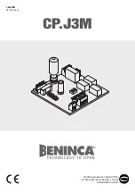
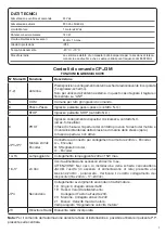
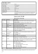
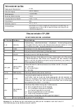
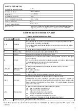
Control units CP.J3M
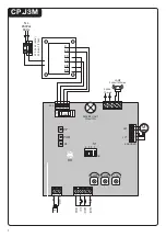
INPUT/OUTPUT FUNCTIONS
Terminals
Function
Description
(1-2)
Antenna
Optional antenna connection to built-in radio receiver board (1-
signal/2-screen).
If external antenna connected cut wire welded to “ANT”.
5
COM
Common for all control inputs.
6
Step by Step
Step by step button input (N.O. contact)
7
STOP
STOP button input (N.C. contact)
8
PHOT
Input for safety devices, N.C. contact (e.g. photocells)
In close cycle: if the contact opens, the motor will stop and will in-
stantly reverse direction (opening).
In open cycle: disabled.
JP1/JP7
24VDC Motor
Encoder
IExtractable connector with connection to 24VDC + Encoder
A: + Encoder
B: S Encoder signal
C: - Encoder
14-15
Blinker
Blinker connection, 24Vac/15W max.
16-17
24 Vac
Accessory power supply 24Vac/1A max.
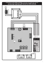
IMPORTANT: If the battery charger board JM.CB is installed, the
output (without mains power connected) has a 24Vdc polarised
voltage. Make sure the devices are correctly connected.
(i.e. 16:+24Vdc - 17:-24Vdc).
JP4
Secondary
Secondary circuit of the transformer.
18 Grey: 0V output
19 Red: Slowdown speed.
Connect the Faston to the 20V output
20 Brown: 24V output
21 White: Motor speed.
See section “Motor speed adjustment ”
J3
Radio Receiver
Built-in radio receiver
N.B.: To control the automation during installation, the Step by Step button on the control unit can be
used.
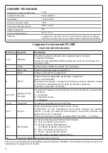
TECHNICAL DATA
Contol unit supply
24 Vdc
Power supply
230 Vac 50/60 Hz
Output supply
1 motor 24Vdc
Power maximum motor
120 W
Output supply accessories
24Vdc 1 A max.
Protection level
IP54
Operating temp.
-20°C / +70°C
Radio receiver
The control unit is fitted with a built-in radio module for receiving remote
controls both with fixed codes and variable codes with a frequency of
433.92MHz.
Содержание CP.J3M
Страница 34: ......
Страница 35: ......
Страница 36: ...AUTOMATISMI BENINCÀ SpA Via Capitello 45 36066 Sandrigo VI Tel 0444 751030 r a Fax 0444 759728 ...

