background image

Fokker


Dr.I


35”


Page


2


Copyright©


2005

13


M.K.


Bengtson


All


Rights


Reserved


Rev


04/13


The


Leading


Edge


of


the


Aileron


The


leading


edge


of


the


aileron


is


rounded


over


with


sandpaper


to


make


the


aileron


movable


with


a


minimum


gap.


The


trailing


edge


of


the


wing


in


that


section


is


left


flat.


FUSELAGE


CONSTRUCTION


The


fuselage


is


built


as


two


separate


box


structures,


the


front


balsa


sheet


and


ply


area


and


the


rear


built


up


section,


which


are


then


joined


over


the


plan.


This


system


not


only


keeps


each


stage


simple,


but


it


also


helps


to


ensure


a


straight


fuselage.


Fuselage


Construction


Detail


Building


of


the


rear


of


the


Fuselage


Begin


by


building


two


rear


fuselage


frames


over


the


plan


and


allow


to


dry.


Select


hard


balsa


or


basswood


for


the


longerons.


Join


the


two


frames


over


the


plan


with


cross


braces


and


the


tailskid


mount.


Check,


check


and


check


again


that


this


and


ALL


other


structures


remain


perfectly


straight


and


square.


Building


of


the


front


of


the


Fuselage


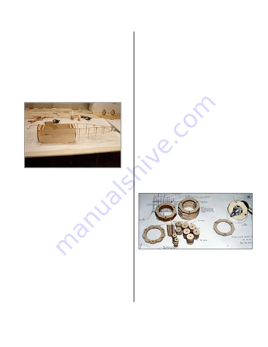
The


front


half


of


the


fuselage


is


a


box


structure


made


from


1/8”


balsa


and


plywood.


Assemble


the


balsa


sides


from


the


two


laser


cut


pieces.


Add


the


1/32”


plywood


doubler


to


the


inside


surfaces.


Using


the


plan


as


a


guide,


build


the


fuselage


over


the


top


view


adding


the


sides


to


the


F1


and


F3


formers.


When


secure,


remove


from


plan


and


add


the


basswood


crosspieces


and


Former


F3a.


Add


the


undercarriage


mounts


F1C


and


F1D.


The


top


deck


formers


are


added


and


the


turtle


decking


is


glued


in


place.


1/16

th


Balsa


sheeting


covers


the


front/top


of


the


fuselage


between


formers


F1


andF2.


The


area


aft


of


this


is


dealt


with


later


in


this


manual.


MOTOR


MOUNT/DUMMY


ENGINE


Items


needed


to


finish


the


motor


mount:


3


2

56


x


2”


machine


screws


Heavy


Card


Stock


paper


String


1/32”


music


wire,


for


push


rods


The


motor


that


will


power


this


model


Find


the


two


1/16”


plywood


motor


mounts


plates.


Compare


the


mounting


pattern


on


the


plate


to


your


motor.


Adjust


the


holes


if


necessary.


Laminate


the


two


plates


together.


Find


the


8


3/16”


balsa


motor


core


pieces.


Laminate


them


together


one


section


of


5


pieces


and


another


section


with


3


pieces.


Check


the


plans


for


correct


order


of


pieces.


Use


the


2

56


screws


to


line


up


the


pieces


properly.


Laminate


the


1/16”


ply


pieces


to


the


3

unit


section,


with


the


1/8”


notched


piece


between


the


5

piece


section.


Mount


your


motor


inside


the


core


unit.


A


hole


for


the


three


motor


wires


to


exit


will


need


to


be


fashioned.


Find


the


three


different


sized


circular


pieces


for


the


engine


cylinders


as


well


as


the


3/32”


square


balsa


center


sticks.


This


builder


made


a


small


fixture


to


glue


the


pieces


square


and


proper


distance


apart.


Assemble


the


9


cylinder


cores.


Cut


9


pieces


of


heavy


paper


from


the


pattern


in


the


lower


left


corner


of


the


plans.


Cut


the


paper


so


the


grain


allows


the


paper


to


be


rolled.


This


builder


pre

rolled


the


paper


around


a


Sharpie


pen.


Glue


the


rolled


paper


around


the


cylinder


cores.


Cut


2


pieces


of


string


about


18”


long,


glue


one


end


of


the


string


to


the


top


or


bottom


of


the


paper


cylinders.


Wind


both


pieces


of


string


around


the


cylinder.


Glue


the


other


Содержание Fokker Dr.I 35"

Страница 1: ...Bengtson All Rights Reserved Rev 04 13 Fokker Dr I 35 R C Scale Model Instructions CONTACT INFORMATION Designed by M K Bengtson Manufactured and Distributed by Bengtson Company e mail sales aerodrome...

Страница 2: ...illustrated are the same John Boeck built the Fokker Dr I prototype COWLING Begin construction of the cowl by gluing C1 and C2 to a strip of 1 32 ply with the grain of the plywood running the short wa...

Страница 3: ...he turtle decking is glued in place 1 16th Balsa sheeting covers the front top of the fuselage between formers F1 andF2 The area aft of this is dealt with later in this manual MOTOR MOUNT DUMMY ENGINE...

Страница 4: ...s w optional horizontal stab center balsa omitted Don t add the horns or hinge the surfaces until after covering is complete LANDING GEAR Landing Gear Trial Fitting The landing gear is made from 1 16...

Страница 5: ...ends is to glue them while they are in place on the wheel Then attach the tires to the wheels and CA in place A thin bead of CA around the rim makes for a secure tire Wheels Paper cones are cut out U...

Страница 6: ...he music wires can be attached either by overlapping them and lashing with thread or have them meet inside a short section of 3 32 brass tubing The top of the fuselage between the middle wings can be...

Страница 7: ...y well or at all 2 Down and right thrust 3 Straight and non warped wings Here are some excerpts of John Boeck s flight report The Fokker Dawn Patrol was in full force this morning ROG s look scale and...

Отзывы: