


20
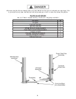
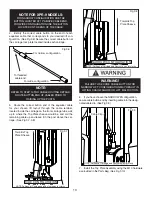
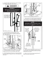
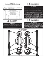
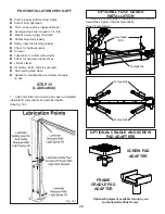
Fig. 12.1
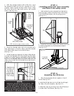
Lift Head
Pin
Lift Head
Pin
Snap
Ring
Snap
Ring
Lift Head
Fig. 12.2
Lift Head
Pin
Lift Head
Pin
Snap
Ring
Snap
Ring
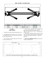
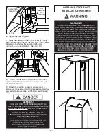
Fig. 12.3
Low Profi le Triple
Telescoping Arm
Assembly
Low Profi le
Medium Arm
Assembly
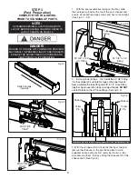
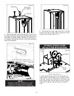
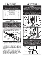
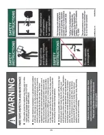
4. Each arm restraint gear can be oriented in a Left
or Right confi guration on the arms. Each arm and arm
restraint gear must be positioned in the proper location in
the lift head. (See Fig. 12.4 & 12.5)
5. Loosen the arm restraint gear bolts and adjust the
arm restraint gears so that the teeth on the gear ring
mesh smoothly with the teeth on the gears of the arm
restraint pin. (See Fig. 12.6)
Fig. 12.4
NOTE: Arm gears rings have
Left and Right orientations
Fig. 12.5
LEFT
RIGHT
NOTE:
LEFT AND RIGHT ARE DETERMINED WHEN FACING
THE INSIDE. OPEN SIDE OF THE LIFT POST.
DANGER!
THE ARM RESTRAINT GEARS MUST BE
POSITIONED AND ADJUSTED PROPERLY.
CONFIRMATION OF PROPER GEAR ENGAGEMENT
MUST BE MADE PRIOR TO THE OPERATION OF THE
LIFT. PERIODIC INSPECTION AND ADJUSTMENT
IS REQUIRED. FAILURE TO INSPECT AND ADJUST
THE ARM RESTRAINT GEARS ON ALL FOUR ARMS
PROPERLY CAN RESULT IN DAMAGE TO THE
VEHICLE OR INJURY AND/OR DEATH.


