background image

89000109-002 

xVue Touch Installation Manual

Rev 2

Page 8-7

© Honeywell International Inc. Do not copy without express permission of Honeywell.

For Use in Non-Certified Aircraft

8.2 KSD 100EXP Touch Calibration

8.2.1 KSD 100EXP Manual Touch Calibration

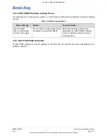
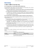
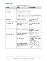
When the manual touch calibration is performed, all touch functionality is disabled except the touches
needed to complete the calibration procedure.

(1) Power on the KSD 100EXP by setting the PFD breaker or turning on the avionics. 
(2) Press Enter on the Database Acknowledge Screen, refer to Figure 6-3.
(3) On the KSD 100EXP screen, Figure 7-1, select the Menu button, Figure 7-2, located at the top right

of the screen.

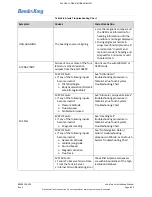
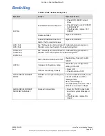
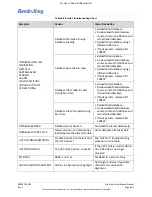
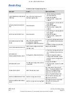
(4) From the Main Menu, Figure 7-6, select the System Tools button.

(5) From the System Tools Menu, Figure 7-13, select the Screen Maint button.

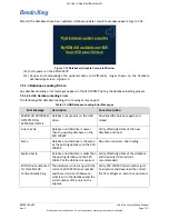
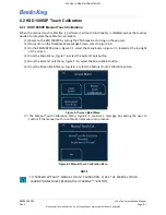
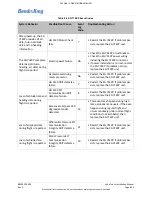
(6) From the Screen Maint Menu, Figure 8-1, select the Manual Touch Calibration button. 

Figure 8-1 Screen Maint Menu

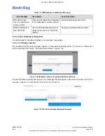
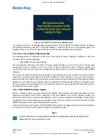
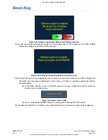
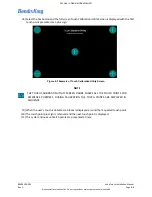
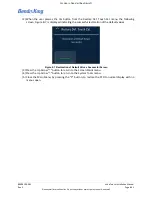
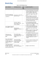
(7)  The  Manual  Touch  Calibration  Menu,  Figure 8-2,  contains  a  message  box  asking  the  user  to

confirm if the manual touch re-calibration procedure can proceed.

Figure 8-2 Manual Touch Calibration Menu

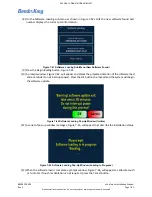
NOTE

TO  PROCEED  WITHOUT  MANUAL  TOUCH  CALIBRATION,  CLOSE  THE  MANUAL  TOUCH

CALIBRATION MENU BY PRESSING THE UP ARROW “^” BUTTON. 

Содержание KG 71EXP

Страница 1: ...7 International Direct XVUE TOUCH PRIMARY FLIGHT DISPLAY SYSTEM INSTALLATION MANUAL FOR USE IN NON CERTIFIED AIRCRAFT Document P N 89000109 002 Rev 2 November 2019 Export Control Thisdocumentcontainst...

Страница 2: ...ever this License Agreement will govern in the event of a conflict between its terms and conditions and those of a purchase order or acknowledgment 1 License Grant If you are a party to an applicable...

Страница 3: ...se Agreement you will return these Materials to Honeywell without retaining any copies and will have one of your authorized officers certify that all Materials have been returned with no copies retain...

Страница 4: ...A Form 174 or equivalent from the manufacturers or suppliers of the materials to be used The user must know the manufacturer supplier data and obey the procedures recommendations warnings and cautions...

Страница 5: ...e in the preparation of this document to assure its accuracy Honeywell assumes no liability resulting from any errors or omissions in this document or from the use of the information contained herein...

Страница 6: ...ircraft RECORD OF REVISIONS NOTE The revision level for every page of this document will be updated during the revision process A list of effective pages is therefore not required Revision Revision Da...

Страница 7: ...m ADAHRS 2 4 2 3 4 KMG 7010 MD32 Magnetometer 2 4 2 3 5 KDC 100EXP Data Converter 2 4 2 3 6 KTP 73 OAT Probe 2 5 2 4 Technical Specifications 2 5 2 5 Environmental Qualification Form EQF 2 9 2 6 Regul...

Страница 8: ...3 22 3 6 6 KCP 100EXP Installation Considerations 3 22 3 6 6 1 KCP 100EXP Location 3 22 3 6 7 KG 71EXP Installation Considerations 3 23 3 6 7 1 KG 71EXP Location 3 23 3 6 7 2 KG 71EXP Orientation 3 24...

Страница 9: ...t Verification 4 11 4 5 KG 71EXP Installation 4 12 4 5 1 KG 71EXP Installation Procedures 4 12 4 5 2 KG 71EXP Post Installation Unit Verification 4 13 4 6 KMG 7010 Installation 4 14 4 6 1 KMG 7010 Ins...

Страница 10: ...23 6 2 3 GPS NAV Configuration Setup 6 23 6 2 3 1 GPS Navigation Source 6 25 6 2 3 2 VLOC Navigation Source 6 26 6 2 4 Autopilot Configuration Setup 6 29 6 2 4 1 AP Computer 6 31 6 2 4 2 Sync FD Offs...

Страница 11: ...heckout 7 13 7 3 EMI Interaction Checkout 7 14 7 4 Post Installation Flight Checks 7 14 7 5 Post Installation Activities 7 14 7 5 1 Database Updates 7 14 7 5 1 1 USB Database Loading 7 15 7 5 1 2 Wi F...

Страница 12: ...4 8 Adjustments 9 8 9 2 4 9 Testing 9 8 9 2 4 10 Lubrication 9 8 9 2 5 Servicing Information 9 8 9 2 6 Troubleshooting 9 8 9 2 7 Storage Limitation 9 8 9 2 8 Removal and Reinstallation Information 9 8...

Страница 13: ...odule Circuit Card Assembly 4 6 Figure 4 8 Bottom Side of J2 Backshell 4 6 Figure 4 9 KSD 100EXP Grip Installation Sheet 1 of 2 4 7 Figure 4 10 KSD 100EXP Grip Installation Sheet 2 of 2 4 8 Figure 4 1...

Страница 14: ...d Keypad Example 6 21 Figure 6 29 Master VOL Sub Menu 6 22 Figure 6 30 TAWS Toggle 6 22 Figure 6 31 GPS NAV Sub Menu 6 23 Figure 6 32 GPS 1 Sub Menu 6 25 Figure 6 33 GPS2 Sub Menu 6 26 Figure 6 34 VLO...

Страница 15: ...bled 7 19 Figure 7 22 Connected to KSD Wi Fi 7 20 Figure 7 23 DataManager Lite Main Page 7 20 Figure 7 24 Wi Fi Webpage with Selected Database 7 21 Figure 7 25 Uploading Databases to KSD 100EXP 7 21 F...

Страница 16: ...ure A 8 KMG 7010 Outline and Mounting Drawing Sheet 1 of 2 A 8 Figure A 9 KMG 7010 Outline and Mounting Drawing Sheet 2 of 2 A 9 Figure A 10 MD32 Outline Drawing A 10 Figure A 11 KDC 100EXP Outline an...

Страница 17: ...egulatory Compliance 2 19 Table 3 1 Pre Installation Checklist 3 3 Table 3 2 xVue Touch System Components and Kits 3 5 Table 3 3 Installation Kit Backshell Assembly KSD 100EXP PN 89000120 002 3 5 Tabl...

Страница 18: ...Viewed from LRU 5 11 Table 5 10 KTP 73 Wire Descriptions 5 12 Table 5 11 Configuration Module J2 Backshell Pin Descriptions 5 12 Table 6 1 Supported Navigation Sources 6 24 Table 6 2 Supported Autopi...

Страница 19: ...ragraph or step Notes follow the applicable paragraph or step 1 1 2 Observance of Manual Instructions 1 Make sure that you carefully obey all safety quality operation and shop procedures for the unit...

Страница 20: ...iption United States GPO Style Manual available at http www gpo gov fdsys pkg GPOSTYLEMANUAL 2008 content detail html 14 CFR Part 43 Title 14 of Code of Federal Regulations 14 CFR Part 43 MAINTENANCE...

Страница 21: ...3 Electrostatic Discharge Control Handbook for Protection of Electrical and Electronic Parts Assemblies and Equipment Excluding Electrically Initiated Explosive Devices Metric available from any milit...

Страница 22: ...aircraft and the CG of the unit installed on the aircraft AS Aerospace Standard ASME American Society of Mechanical Engineers AWG American Wire Gauge A429 ARINC 429 Data Transfer Standard BL Backligh...

Страница 23: ...on System ESD Electrostatic Discharge ESDS Electrostatic Discharge Sensitive EGPWS Enhanced Ground Proximity Warning System EQF Environmental Qualification Form ETH Ethernet F Fahrenheit FAA Federal A...

Страница 24: ...r second kg Kilogram kPa Kilopascal KT Knots lb Pound LED Light Emitting Diode Lgnd Legend LOC Localizer LRU Line Replaceable Unit m Meter Mbit Megabit MEMS Micro Electromechanical Sensors MIL Militar...

Страница 25: ...Radio Technical Commission for Aeronautics RTD Resistance Temperature Detectors RTN Return RX Receive s Second SDI Serial Digital Interface SEL Select SI International System of Units SN Serial Numbe...

Страница 26: ...metallic aircraft refers to all other aircraft fiberglass or composite skin and aircraft with tube and fabric construction UAT Universal Access Transceiver USB Universal Serial Bus USMS United States...

Страница 27: ...fication of non type certificated aircraft to install the xVue Touch This installation manual is not a substitute for an approved airframe specific flight and or maintenance manuals installation drawi...

Страница 28: ...P Data Converter included with MD32 Magnetometer 6 KTP 73 Outside Air Temperature OAT Probe 7 Configuration Module The xVue Touch System is depicted in Figure 2 1 and Figure 2 2 Figure 2 1 xVue Touch...

Страница 29: ...r glove The display has a light sensor that detects cockpit lighting conditions for automatic dimming of the display Dimming can also be controlled manually The KSD 100EXP includes a USB port for data...

Страница 30: ...speed ARINC The KG 71EXP communication with the KMG 7010 Magnetometer is via a dedicated Controller Area Network CAN bus The KG 71EXP communication with the MD32 Magnetometer is via the KDC 100EXP da...

Страница 31: ...p and 32 2VDC max Circuit Breaker 2 AMP for 28 VDC 3 AMP for 14 VDC systems Cooling Convection cooled does not required forced air cooling within the unit operational temperature range refer to Sectio...

Страница 32: ...thin the unit operational temperature range refer to Section 3 6 7 3 for cooling considerations Connectors Male 50 pin D sub Female 9 pin D sub Maintenance port Table 2 5 KG 71EXP ADAHRS Performance C...

Страница 33: ...25 C after 2 minute warmup 200 mA Nominal 55 C after 2 minute warmup 700 mA Maximum 55 C Typical 28VDC 0 08 AMP Typical 14VDC 0 16 AMP Circuit Breaker 1 AMP for 28 VDC 2 AMP for 14 VDC systems Signal...

Страница 34: ...mA Maximum 55 C Circuit Breaker 1 AMP for 28 VDC 2 AMP for 14 VDC systems Signal Inputs Outputs Serial CAN Bus Cooling Convection cooled No external cooling required Connector Male 15 pin Certificati...

Страница 35: ...pplicable 5 0 Temperature Variation C 2 C minute 6 0 Humidity A 7 0 Operational Shocks and Crash Safety B A C Type 3 Test R 8 0 Vibration S curve M Zone 2 9 0 Explosive Atmosphere X 10 0 Waterproofnes...

Страница 36: ...oprene with horizontal burn Test Bezel Seal Neoprene Cord with horizontal burn 4 Conducted Susceptibility CS testing was performed using DO 160E Cat A per FAA Policy PS ACE 23 10 5 Radiated Susceptibi...

Страница 37: ...perational Shocks and Crash Safety B A C Type 3 Test R 8 0 Vibration S curve M Zone 2 9 0 Explosive Atmosphere X 10 0 Waterproofness X 11 0 Fluids Susceptibility X 12 0 Sand and Dust X 13 0 Fungus Res...

Страница 38: ...rizontal burn 4 Conducted Susceptibility CS testing was performed using DO 160E Cat A per FAA Policy PS ACE 23 10 5 Radiated Susceptibility RS testing was performed using the following levels per FAA...

Страница 39: ...nal Shocks and Crash Safety B See Note 4 Aircraft Type 3 Test F 8 0 Vibration S curve M 9 0 Explosive Atmosphere X 10 0 Waterproofness Y Condensing water 11 0 Fluids Susceptibility X 12 0 Sand and Dus...

Страница 40: ...erformed using DO 160E Cat A per FAA Policy PS ACE 23 10 6 Radiated Susceptibility RS testing was performed using the following levels per FAA Policy PS ACE 23 10 7 The Outside Air Temperature OAT par...

Страница 41: ...Vibration S curves E L M T R curve G See Note 1 Fixed Wing Zone 5 Helicopter Zone 1b 9 0 Explosive Atmosphere E Environment II Supplemental Analysis Performed beyond DO 160D DO 160G Section 9 analysi...

Страница 42: ...0 Lightning Direct Effects X Not Tested 24 0 Icing A 25 0 Electrostatic Discharge ESD A N A Fire Flammability Not Applicable Supplemental Testing beyond DO 160D DO 160G Section 26 Cat C Labels only HP...

Страница 43: ...EE1 9 0 Explosion X 10 0 Waterproofness W 11 0 Fluids X 12 0 Sand and Dust X 13 0 Fungus Resistance X 14 0 Salt Fog S 15 0 Magnetic Effect Z 16 0 Power Input Z 17 0 Voltage Spike A 18 0 Audio Frequenc...

Страница 44: ...able 5 0 Temperature Variation A 10 C per minute 6 0 Humidity C 7 0 Operational Shocks and Crash Safety A 6 g 11 ms Pulse Crash Safety Impulse Sustained no test performed 8 0 Vibration S Curve M T Zon...

Страница 45: ...6 Regulatory Compliance Table 2 17 xVue Touch System Component Regulatory Compliance Component Function Approval Type KSD 100EXP Display PMA KCP 100EXP Display Control PMA KG 71EXP Air Data Attitude a...

Страница 46: ...lateral map display at the location corresponding to the obstacle latitude and longitude 2 7 4 Terrain Database The Terrain Database is used to render the terrain to create a realistic view of the te...

Страница 47: ...standby instruments provide a secondary reference altitude altimeter and airspeed indication 2 10 Required GPS Navigator Installation of the xVue Touch System requires at least one GPS SBAS navigator...

Страница 48: ...2 xVue Touch Installation Manual Rev 2 Page 2 22 Honeywell International Inc Do not copy without express permission of Honeywell For Use in Non Certified Aircraft Figure 2 3 Standby Instrument Power R...

Страница 49: ...rn Refer to the troubleshooting instructions in Section 8 Troubleshooting If repair is necessary the unit must be sent to a BendixKing certificated repair facility The xVue Touch System components are...

Страница 50: ...the installation considerations in Section 3 6 along with the installation procedures in Section 4 as they are presented to accomplish a successful installation Read the entire sections before beginn...

Страница 51: ...SCHARGE SENSITIVE ESDS DEVICES ESDS DEVICES ARE SUBJECT TO DAMAGE BY EXCESSIVE LEVELS OF VOLTAGE AND OR CURRENT THE LOW ENERGY SOURCE THAT MOST COMMONLY DESTROYS ESDS DEVICES IS THE HUMAN BODY WHICH I...

Страница 52: ...h the xVue Touch System Section 3 6 1 xVue Touch System Interfaces Acceptable KSD 100EXP instrument panel location within the primary field of view Section 3 6 5 KSD 100EXP Installation Considerations...

Страница 53: ...Audio Panel and Section 6 2 2 3 Master Audio Volume Installation operational limitations reviewed to ensure no adverse impact to the installation Section 2 11 Installation Limitations Section 9 2 2 A...

Страница 54: ...Connectors Install Kit 89000120 003 KSD 100EXP Mounting Hardware and Grip Install Kit 89000120 007 KCP 100EXP Control Panel Install Kit for Portrait Mounting 89000126 004 KCP 100EXP Control Panel Inst...

Страница 55: ...ctor Contact Crimp Socket Size 22 78 EA Table 3 5 Installation Kit Mounting Hardware and Grip KSD 100EXP PN 89000120 007 Part Number Description Qty UM 89500020 024 KSD 100EXP Grip 1 EA MS51957 1B 2 5...

Страница 56: ...ruction For Harness Assembly Parts REF REF 010 00068 0002 Crimp Terminal 4S 1 EA 030 01157 0011 Socket Crimp 20G 9 EA 030 01499 0011 Connector D Sub Hood EMI RFI Metal Jackscrews 9 Pos 1 EA 057 05944...

Страница 57: ...d MD32 and performing the post installation compass verification Table 3 13 Installation Materials Required but Not Supplied Description PN or Specification Quantity Note Wire 22 20 18 16 AWG M22759 1...

Страница 58: ...is maintained Nutplates 4 40 MS21069L04 or MS21071L04 4 Orientation is optional as long as minimum edge distance is maintained Rivets MS20426AD3 X 16 X size 10 32 Rivet nuts NAS1329A3KXX 4 XX size St...

Страница 59: ...ter Equivalent inclinometer with accuracy of 0 1 degrees Commercially Available Pitot static tester Commercially Available NAV ILS Signal Generator Commercially Available Aircraft Power Unit Commercia...

Страница 60: ...XP ADAHRS Installation Kit 89000123 007 M81969 1 04 RED and White Metal Insert Removal Tools AMF8 Crimp Tool M22520 2 01 K13 1 Crimper Turret Head Positioner M22520 2 08 D sub 9 Socket Connector Tools...

Страница 61: ...1 Discrete Inputs Refer to the tables below for the discrete input states Table 3 15 KSD 100EXP Discrete Input Ground Open DIGO States State Voltage Level Active 0 VDC Inactive Open Circuit Table 3 16...

Страница 62: ...ta rate on this bus is 1 Mbit s 3 6 Installation Considerations In general equipment must be installed in a location convenient for operation inspection and maintenance and in an area free from excess...

Страница 63: ...9 002 xVue Touch Installation Manual Rev 2 Page 3 14 Honeywell International Inc Do not copy without express permission of Honeywell For Use in Non Certified Aircraft Figure 3 2 xVue Touch System Inte...

Страница 64: ...e may be other devices that can be configured the same as the ones listed below but have not been tested by BendixKing Table 3 22 xVue Touch Compatible Equipment Category Vendor Model Audio Panel Bend...

Страница 65: ...GTN 725 Avidyne IFD 410 IFD 510 IFD 545 Radio Navigators BendixKing KX 155 KX 155A KX 165 KX 165A Garmin GNC 255 GPS Radio Navigators BendixKing KSN 770 Garmin GNS 430W GNS 530W GTN 650 GTN 750 Avidy...

Страница 66: ...inches For airplane with original panel thickness of 0 063 inches or greater the new panel thickness must match the original panel Magnetometer BendixKing KMG 7010 Magnetometer MidContinent Instrument...

Страница 67: ...Either two inch or three inch standby instruments may be used 3 6 3 1 Standby Instrument Location Standby instrument locations are recommended per AC 23 1311 1C Section 15 to be within 35 degrees fro...

Страница 68: ...ASI needs a battery pack or an emergency power system that meets the 30 minute operational requirement 3 6 3 4 Standby Altimeter The existing airplane altimeter must be retained for use as a standby...

Страница 69: ...guidance and are recommended for the xVue Touch System installation The primary field of view is measured in both the horizontal and vertical fields as illustrated in Figure 3 3 reference AC 23 1311 1...

Страница 70: ...struments is 0 5 inch 12 7 mm from the top or bottom of the KSD 100EXP cutout to the instrument 2 The installed location is away from heat sources including electronic instruments Heat generating sour...

Страница 71: ...y the KG 71EXP is not the lowest point in the pitot static system to reduce the chance of allowing moisture to enter the unit The locations chosen for the KG 71EXP and the method of installation will...

Страница 72: ...must be leveled with the airplane s pitch and roll within 15 degrees Many airplane models have an airplane level reference shelf that is in alignment with the actual airplane s pitch and roll level A...

Страница 73: ...es of the level airplane The KMG 7010 MD32 should be located as far as possible from all sources of magnetic disturbance or ferrous materials such as nickel iron steel cobalt or magnetic field inducin...

Страница 74: ...ter is located alongside it Isolate the specific electrical device causing the current and ground the device using a wire rather than the airframe The wire should be routed alongside the devices power...

Страница 75: ...llation orientations 3 6 10 KTP 73 Installation Considerations 3 6 10 1 KTP 73 Location To ensure accurate temperature readings the KTP 73 OAT probe must be mounted to the wing or fuselage and away fr...

Страница 76: ...f the airplane structure sufficient to extend the tip into the free stream Ensure adequate space for sensor lead cable routing is available Refer to the airplane maintenance manual for additional info...

Страница 77: ...d be connected to the essential bus If the airplane has more than one essential bus the xVue Touch System components should be connected to one essential bus and the electronic standby instruments con...

Страница 78: ...d the nearest airframe grounding point Electrical bonding begins with the equipment attach point s such as the mounting rack or the instrument panel Ensure good metal to metal bonding as brackets and...

Страница 79: ...lateral and vertical deviation from GPS sources and navigation receivers in the airplane It is not recommended to use external CDI in conjunction with the xVue Touch System External serial data source...

Страница 80: ...th the existing autopilot on the airplane must be retained and may require relocation refer to AC 23 1311 1C Due to space constraints it may be necessary to blind mount the unit The installer must ens...

Страница 81: ...Ensure the instrument panel is prepared per Section 3 6 2 and the locations for the KSD 100EXP PFD and KCP 100EXP Control Panel are determined based on considerations in Section 3 6 5 and Section 3 6...

Страница 82: ...ttach to the P1 upper and P2 lower wiring harness connectors refer to Figure 4 1 Each 78 pin D sub connector housing provided in the KSD 100EXP Installation Kit Configuration Module And Connectors is...

Страница 83: ...ms and part descriptions See Table 5 1 KSD 100EXP J1 Pin Descriptions Viewed from LRU for pin designations Figure 4 3 KSD 100EXP J1 Connector Assembly Using the KSD 100EXP Installation Kit Backshell A...

Страница 84: ...ottom Side of J2 Backshell Torque screws to 4 0 4 in lbs 0 45 0 05 Nm 4 3 1 2 J2 Connector Configuration Module Assembly The KSD 100 J2 Connector Configuration Module Assembly mounts to the lower D Su...

Страница 85: ...per J STD 001 to the Configuration Module CCA provided in the KSD 100EXP Installation Kit Configuration Module using Table 4 1 Configuration Module J2 Backshell Pin Descriptions Table 4 1 Configurati...

Страница 86: ...ewed from LRU 6 Insert the seven socket connector contacts from the Configuration Module into J2 housing per Table 4 1 Configuration Module J2 Backshell Pin Descriptions 7 Inside the backshell base in...

Страница 87: ...ocedures 1 Prepare the KSD 100EXP for installation a Using the KSD 100EXP Mounting Hardware and Grip Installation Kit install the Santoprene Grip by sliding the grip from the back of the KSD 100EXP an...

Страница 88: ...been prepared per Section 4 2 3 Ensure all power is removed from the airplane 4 Verify grounding for the KSD 100EXP see note below If utilizing the center ground stud located on the back of the KSD 10...

Страница 89: ...10 Electrical Bonding Considerations 7 Install the KSD 100EXP into the instrument panel while ensuring that the USB port is located on the left side of the unit from the pilot s perspective and secur...

Страница 90: ...ions refer to Figure A 5 4 4 1 KCP 100EXP Instrument Panel Installation Procedures 1 Ensure all wiring and power checks have been completed per Section 6 1 2 Ensure airplane instrument panel has been...

Страница 91: ...nting hole locations b Install Center Stack Adapter using the four 6 32 pan head screws and clip nuts refer to Figure 4 13 KCP 100EXP Landscape Center Stack Installation 6 Install the KCP 100EXP to th...

Страница 92: ...educe airplane vibration effects 4 Prepare mounting rivet nut locations as bonding points such that the bonding resistance conforms to the guidelines listed in Section 3 10 Electrical Bonding Consider...

Страница 93: ...12 Attach the pitot and static lines to their corresponding fitting on the KG 71EXP 60 in lbs 6 8 Nm maximum DO NOT OVERTIGHTEN The KG 71EXP is labeled PITOT and STATIC at the fitting sites to provid...

Страница 94: ...nector The only restriction is that once the KMG 7010 is installed the KMG 7010 pitch and roll offsets should be within 5 degrees from the airplane pitch and roll The total count of acceptable install...

Страница 95: ...the three KMG 7010 primary axes are parallel within 5 degrees of the longitudinal lateral and vertical axes of the level airplane The KMG 7010 may be mounted parallel to the lateral pitch longitudina...

Страница 96: ...ll the MD32 Magnetometer per its installation manual see Appendix D MD32 Installation Manual 4 7 1 MD32 Post Installation Unit Verification Accomplish the following steps in this manual before return...

Страница 97: ...d 7 Apply conversion coating material conforming to MIL C 81706 per AC 43 13 1B to exposed metal surfaces 8 Install mounting adapter plate as applicable 9 Using the KDC 100EXP Installation Kit mount t...

Страница 98: ...Certified Aircraft 13 Verify the electrical bond between the KDC 100EXP and the airframe conforms to the guidelines listed in Section 3 10 Electrical Bonding Considerations Verify the electrical bond...

Страница 99: ...t skins from 0 016 to 0 032 inch thickness The number rivets can be increased and shape of the doubler modified to suit the particular installation For thicker skins a separate approval is required Do...

Страница 100: ...ugh to enable maintenance personnel to troubleshoot repair and service the electrical system The diagrams should also include a method of determining the connector type if other than the connectors su...

Страница 101: ...n the Type Certificate Data Sheet TCDS and airplane specification s The various xVue Touch System components and associated nominal weights are listed in Table 4 3 below Note The connector and backshe...

Страница 102: ...tified Aircraft KMG 7010 Magnetometer 065 00189 0101 0 9 0 41 See Figure A 8 MD32 Magnetometer 6420032 0 19 0 085 N A KDC 100EXP Data Converter 89000138 001 0 9 0 41 See Figure A 8 KTP 73 OAT Probe 89...

Страница 103: ...if published in the Airplane Flight Manual In addition in the event of a complete loss of the primary electrical system the battery s must be capable of providing at least 30 minutes of electrical po...

Страница 104: ...ed in Table and should be used for the ELA values Verify the aircraft electrical load does not exceed 80 of the alternator generator data plate rated capacity or the maximum load value if published in...

Страница 105: ...3_RX_H In Reserved 7 WX_RADAR_A429_TX_A Out Reserved 8 UAT_WX_RS232_RX In Included 9 UAT_WX_RS232_TX Out Included 10 NAV1_2_ROLL_STR_VAL_DO28VO Out Reserved 11 NAV1_ROLL_STR_VALID_DI28VO In Reserved 1...

Страница 106: ...SPARE_A429_RX_B In Reserved 41 SPARE_A429_RX_A In Reserved 42 KA_52 57_P15V_PWR PWR Reserved 43 AFCS_DATUM_VAL_DO5VO Out Reserved 44 AFCS_CRS_DATUM_OUT Out Included 45 AFCS_CMD_BAR_RTRCT_DI15VO In Inc...

Страница 107: ...72 NAV_FLAG_ Out Included 73 NAV_DEV_ _RT Out Included 74 AFCS_HDG_DATUM_OUT Out Included 75 TRANSPONDER_A429_RX_B In Reserved 76 TRANSPONDER_A429_RX_A In Reserved 77 ADAHRS2_A429_TX_B Out Reserved 78...

Страница 108: ...KINGBUS_CLK_DI5VO In Reserved 27 AFCS_KINGBUS_DATA_DI5VO In Reserved 28 AFCS_KINGBUS_STROBE_DI5VO In Reserved 29 SXM_WX_RS422_RX_A In Reserved 30 SXM_WX_RS422_RX_B In Reserved 31 SXM_WX_RS422_TX_A Out...

Страница 109: ...TN GND Included 60 NAV_DEV_ _RT_IN In Reserved 61 NAV_DEV_ _LT_IN In Reserved 62 NAV_FLAG_ _IN In Reserved 63 NAV_FLAG_ _IN In Reserved 64 APM_DATA_MISO In Included 65 APM_DATA_MOSI Out Included 66 AP...

Страница 110: ...3 KCP 100EXP J1 Pin Descriptions Viewed from LRU 5 3 KG 71EXP 5 3 1 KG 71EXP Connector J71 The electrical interface for the KG 71EXP is provided via the 50 pin D Sub connector referenced as J71 Table...

Страница 111: ...5 Temp Probe 2 In 16 Temp Probe 3 In 17 Not Used N A 18 Power GND In 19 Power GND In 20 Power GND Spare In 21 RS 232 Ch0 TXD Out 22 RS 232 Ch0 RTS Out 23 RS 232 Ch0 RXD In 24 RS 232 Ch0 CTS In 25 DGND...

Страница 112: ...Pressure Port Fitting s Figure 5 1 Pressure Port Fitting s 43 A429 TX1 A Out 44 A429 TX1 B Out 45 Chassis GND GND 46 CAN H In 47 CAN L In 48 A429 TX2 B Out 49 Interlock 1 In 50 Interlock 2 In Table 5...

Страница 113: ...for the KMG 7010 is provided via the 9 pin DB 9 connector referenced as J7010 Details about the J7010 connector interface are shown in Table 5 7 Table 5 7 KMG 7010 DB 9 Pin Descriptions Viewed from L...

Страница 114: ...5 2 KMG 7010 Backshell 5 5 MD32 The electrical interface for the MD32 is provided via the 9 pin DB 9 connector Table 5 8 Table 5 8 MD32 DB 9 Pin Descriptions Viewed from LRU Pin Description I O 1 Grou...

Страница 115: ...ble 5 9 Table 5 9 KDC 100EXP Pin Descriptions Viewed from LRU Figure 5 3 KDC 100EXP Backshell Pin Description I O 1 Magnetometer 429 RX HI In 2 Magnetometer 429 RX LO In 3 Ground NC 4 Magnetometer CAN...

Страница 116: ...rtified Aircraft 5 7 KTP 73 5 8 Configuration Module Table 5 10 KTP 73 Wire Descriptions Wire Color Description I O Red TEMP3 Out Black TEMP1 Out White TEMP2 Out Table 5 11 Configuration Module J2 Bac...

Страница 117: ...le the KSD 100EXP will display the Database Acknowledge Screen see Figure 6 3 The maintenance technician may enter the Installation Maintenance Menu from this page The KSD 100EXP PFD has one dedicated...

Страница 118: ...ouch Installation Manual Rev 2 Page 6 2 Honeywell International Inc Do not copy without express permission of Honeywell For Use in Non Certified Aircraft Figure 6 1 KSD 100EXP Installation Maintenance...

Страница 119: ...ess must be checked for proper connections to the airplane power bus Point to point continuity must be checked to identify any faults such as shorting to ground Any faults or discrepancies must be cor...

Страница 120: ...only accessible on ground from the Database Acknowledge Screen Figure 6 3 or the APM Mismatch Error Screen Figure 6 4 To access Config Mode apply the following touch sequence 1 Touch the B on the Ben...

Страница 121: ...Installation Manual Rev 2 Page 6 5 Honeywell International Inc Do not copy without express permission of Honeywell For Use in Non Certified Aircraft Figure 6 4 APM Configuration Mismatch Screen Figure...

Страница 122: ...onfiguration settings in the Installer Main Menu Fields which have been changed are displayed in a green font Figure 6 6 Configuration Preview Window The Installer Main Menu on the left side of the Co...

Страница 123: ...Non Certified Aircraft button is available on the top left side of each of the sub menus Selecting the Back Arrow button will return to the previous active menu Only upon pressing the Save Exit butto...

Страница 124: ...Use in Non Certified Aircraft 6 2 1 System Configuration Setup The System Config button allows the technician to configure the following parameters as shown in Figure 6 8 1 Lighting 2 External Dimmin...

Страница 125: ...ay the System Config sub menu Figure 6 8 2 To change lighting configuration press the Lighting button to display the Lighting sub menu and select between 28 VDC and 14 VDC shown in Figure 6 9 Figure 6...

Страница 126: ...htness level is appropriately balanced with the other cockpit instruments Note Default value is 1 e With the external lighting control at its minimum value set the KCP Lgnd Legend min value by touchin...

Страница 127: ...buttons to adjust the Display backlight so the maximum brightness level is appropriately balanced with the other cockpit instruments Note Default value in 80 e With the external lighting control at it...

Страница 128: ...1 3 Aircraft Tail Number 1 From the System Config sub menu Figure 6 8 press the A C Tail button 2 Using the alpha numeric keyboard shown in Figure 6 13 input the aircraft tail number and press the En...

Страница 129: ...Keypad 3 Verify that the Serial Number is reflected correctly on the Aircraft Serial button as illustrated in Figure 6 16 Figure 6 16 A C Serial 6 2 1 5 Aircraft Pitch Bias Pitch bias function provide...

Страница 130: ...tem Config sub menu Figure 6 8 when the Pilot V Spd indicator shows Locked the Configurable Pilot V Speed settings on the PFD menu cannot be modified The avionics installer should use the following pr...

Страница 131: ...e Back Arrow button to exit the System Config sub menu and return to the Installer Main Menu Figure 6 7 6 2 1 8 Units Configuration The Units configuration is accessed from the System Config sub menu...

Страница 132: ...Config sub menu Figure 6 8 3 Press the Back Arrow button to exit the System Config sub menu and return to the Installer Main Menu Figure 6 7 6 2 2 PFD Configuration Setup The PFD button allows the tec...

Страница 133: ...figuration options include 2000 fpm 3000 fpm 4000 fpm The VSI Range configuration is accessed from the PFD sub menu Figure 6 23 and the current VSI Range is shown on the VSI button Pressing the VSI bu...

Страница 134: ...st be less than or equal to VNE 3 VFE Maximum Flaps Extended speed top of white band 4 VS1 No Flaps Stall speed A green band is displayed on the airspeed tape between VS1 and VNO VS1 must be less than...

Страница 135: ...MANUAL AFM PILOT S OPERATING HANDBOOK POH OR OTHER LEGAL DOCUMENTATION E G PLACARDS NOTE THE V SPEED UNITS ARE DEFINED IN SECTION 6 2 1 8 UNITS CONFIGURATION AND THE V SPEED VALUES ARE CLEARED IF THE...

Страница 136: ...press the Airspeed button to display the Airspeed sub menu Figure 6 27 Figure 6 27 Airspeed Sub Menu 2 From the Airspeed sub menu press the desired V Speed button to display the V Speed Keypad NOTE AN...

Страница 137: ...the modified V Speed button on the Airspeed sub menu Figure 6 27 5 After the V Speeds are entered press the Back Arrow button to return to the PFD sub menu 6 2 2 3 Master Audio Volume 1 From the PFD s...

Страница 138: ...ther system s and adjust as needed 6 Press the Back Arrow button to return to the PFD sub menu 6 2 2 4 Terrain Awareness and Warning System TAWS Toggle The TAWS configuration is used to indicate if an...

Страница 139: ...altitude preselect configuration is used to indicate whether the KSD 100EXP PFD pilot selected altitude function is enabled or disabled If the airplane is already equipped for a pilot selectable altit...

Страница 140: ...avigators two digital VHF Navigator radios and one analog legacy VHF Navigator radio A GPS Navigator and VHF Navigator may be integrated in a single unit In addition to the ARINC 429 data the KSD 100E...

Страница 141: ...avigator and will process and monitor all analog signals provided by the Analog VHF Navigator The default configuration for the VHF Navigator analog interface is Not Connected In this configuration th...

Страница 142: ...ted LRU is reflected correctly on the GPS2 button shown in Figure 6 31 6 2 3 2 VLOC Navigation Source NOTE THE XVUE TOUCH WILL AUTOMATICALLY SET THE NAVIGATION RADIO SOURCE VLOC 1 OR 2 WHEN THE SELECT...

Страница 143: ...6 34 3 Press the Back Arrow button to return to the GPS NAV sub menu 4 Verify that the selected LRU is reflected correctly on the VLOC1 button shown in Figure 6 31 5 If there is a second NAV radio ins...

Страница 144: ...tified Aircraft Figure 6 35 VLOC2 Sub Menu 6 Press the button for the installed LRU option from the VLOC2 sub menu Figure 6 35 7 Press the Back Arrow button to return to the GPS NAV sub menu 8 Verify...

Страница 145: ...ation Setup The Autopilot button allows the technician to configure the following parameters as shown in Figure 6 36 1 Autopilot LRU 2 Sync FD Offset 3 Sync FD Gain 4 GPSS K Factor Figure 6 36 Autopil...

Страница 146: ...nected The KSD 100EXP in this configuration does not drive outputs for a legacy autopilot and related monitoring is deactivated Only the analog autopilot interface is supported The technician must con...

Страница 147: ...gure 6 36 press the AP Computer button to display the AP Computer sub menu Figure 6 37 l Figure 6 37 AP Computer Sub Menu 2 Press the button for the installed LRU option from the AP Computer sub menu...

Страница 148: ...tor adjusts the Heading Datum Roll Steering relationship from 50 GPSS K Factor of 0 5 to 200 GPSS K Factor of 2 0 with 10 resolution Use the following procedure for setting the GPSS K Factor 1 Create...

Страница 149: ...mission of Honeywell For Use in Non Certified Aircraft Figure 6 39 GPSS K Factor Keypad 5 Using the keypad input the new value for the GPSS K Factor and press the Enter button 6 Verify that the new GP...

Страница 150: ...6 41 Broadcast WX Sub Menu 2 From the Broadcast WX sub menu Figure 6 41 press the Broadcast WX button Table 6 3 Supported Broadcast WX Sources Manufacturer Model BendixKing KGX 130x KGX 150x FreeFligh...

Страница 151: ...t LRU sub menu Figure 6 42 4 Press the Back Arrow button to return to the Broadcast WX sub menu 5 Verify that the selected Broadcast LRU is reflected correctly on the Broadcast WX button shown in Figu...

Страница 152: ...on to display the Traffic sub menu Figure 6 43 Figure 6 43 Traffic Sub Menu 2 From the Traffic sub menu Figure 6 44 press the ADS B Traffic button Figure 6 44 ADS B Sub Menu 3 Press the button for the...

Страница 153: ...the KG 71EXP is physically installed into the airplane and the wiring complete and verified complete the following configuration steps 1 Maintenance Interface Configuration 2 KG 71EXP Installation Ori...

Страница 154: ...operated by the technician The KG 71EXP should be powered off when the USB to RS 232 cable is connected to the maintenance port The CMT application should be started after the PC is connected to the...

Страница 155: ...ilt angles offsets must be configured and stored as a first step during the unit configuration The KG 71 tab provides two sub tabs 1 Installation in Airframe 2 Digital I O The tab Installation in Airf...

Страница 156: ...ned the pitch angle and roll angle are measured and displayed If the KG 71EXP pitch and roll offsets are installed within 15 degrees and the detected pitch and roll angle are within 1 degree typically...

Страница 157: ...The Digital I O tab illustrated in displays the KG 71EXP I O configuration and provides means to modify the I O setup The KG 71EXP has a dedicated receive channel Rx0 for the PFD and the SDI must be s...

Страница 158: ...10 11 The value must be the same as the SDI of labels which are provided by the GPS Navigator 2 GPS Standard a GAMA if GPS meets the GAMA standard common for General Aviation GPS navigators b ARINC 74...

Страница 159: ...r as the Tx channel which is dedicated for communication with the KSD 100EXP 6 3 1 3 2 Attitude Heading The transmit channel can be configured to support existing AHRS systems with a basic set of atti...

Страница 160: ...80 Hz 2 325 Roll Angle transmit rate 80 Hz 6 3 1 3 6 Altitude Interface The transmit channel can be configured to support existing systems with an altitude data set This configuration sets transmit ch...

Страница 161: ...dy Longitudinal Acceleration BNR 80 332 Body Lateral Acceleration BNR 80 333 Body Normal Acceleration BNR 80 336 Inertial Pitch Rate BNR 80 337 Inertial Roll Rate BNR 80 340 Inertial Yaw Rate BNR 80 3...

Страница 162: ...ct any combination of AHRS and ADC labels to send out If the rate for the label is selected the label will be transmitted at that rate Once ARINC Bus Speed and all required labels and rates are select...

Страница 163: ...erface can be configured to use one of the following protocols 1 Icarus 10 2 Icarus 100 3 SHADIN S 4 SHADIN M 5 BendixKing Format C 6 4 KMG 7010 MD32 Calibration Magnetometer The KG 71EXP system suppo...

Страница 164: ...Location MD32Mounting Location MD32Connector Location KMG CMT Image Up Back Down Right 7 Up Left Down Back 16 Up Front Down Left 3 Up Right Down Front 15 Down Back Up Left 5 Down Left Up Front 14 Down...

Страница 165: ...6 4 1 Magnetometer Installation Orientation Figure 6 53 KMG 7010 Calibration Page As shown in Figure 6 53 once the mounting orientation is selected the technician must enter the measured pitch offset...

Страница 166: ...ometer offsets have been entered and while aircraft is leveled the maintenance connection can be disconnected and the KG 71EXP circuit breaker can be cycled and pitch and roll should be displayed as z...

Страница 167: ...uired heading value it should begin with 360 degrees 4 Once the airplane is physically oriented to the specified heading wait 30 60 seconds for the reading to stabilize NOTE BEFORE THE MAGNETOMETER CA...

Страница 168: ...ng button on the CMT screen 6 Verify that the Measured Heading value is within 9 degrees a If the value is within range press the Confirm Reading button refer to Figure 6 55 b If the value is out of t...

Страница 169: ...heading values displayed on the PFD orienta tion in 4 directions North 90 180 and 270 degrees Verify accuracy of 2 degrees of the air plane s orientation and verify drift from each of the target head...

Страница 170: ...hed before proceeding to the ground and flight tests 7 1 Recommended Test Equipment The following test equipment is recommended to complete the post installation checkout procedures in this section 1...

Страница 171: ...ith the pitot static tester connect the tester to the airplane pitot static system and perform a leak check of the system This may be conducted concurrently with the Altitude Display Vertical Display...

Страница 172: ...ter is achieved and stabilized verify that the KSD 100EXP altitude tape and standby altimeter display the same altitude as the pitot static tester the tolerance listed in 14 CFR Part 43 Appendix E Tab...

Страница 173: ...irspeed Labels button Figure 7 4 and ensure that Airspeed Labels are toggled on Figure 7 3 PFD Setup Sub Menu Figure 7 4 Airspeed Labels Button 2 Verify the airspeed units KTS OR MPH set during the co...

Страница 174: ...S display or through the GPS status page available on most GPS systems 3 On the Navigator clear any existing Flight Plan and enter a Direct To waypoint with a known location relative to the airplanes...

Страница 175: ...2 Page 7 6 Honeywell International Inc Do not copy without express permission of Honeywell For Use in Non Certified Aircraft 9 From the Menu Figure 7 6 press the PFD button to launch the PFD Menu Figu...

Страница 176: ...t the Bearing 1 source to GPS1 Figure 7 9 Figure 7 9 Pointer 1 Sub Menu 12 From the Pointer 1 sub menu press the Up Arrow button to return to the Bearing Pointers sub menu 13 From the Bearing Pointers...

Страница 177: ...ointer matches the Bearing Pointer 1 and Bearing Pointer 2 21 On the KCP 100EXP rotate the CRS knob counterclockwise such that the CDI course pointer is to the left of the GPS1 bearing 22 From the KSD...

Страница 178: ...nu Figure 7 8 press the Pointer 2 button and set the source to VLOC1 Figure 7 9 12 Close the Main Menu by pressing the X button to return to the KSD 100EXP screen 13 On the VHF Radio Tester set the mo...

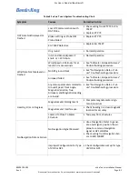
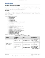
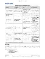
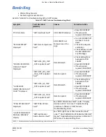
Страница 179: ...EXP PFD screen verify the following a Verify the CDI source is set to VOR1 displayed in green b Verify the CDI course deviation is deflected right at the first deviation scale dot 5 degree dot 25 On t...

Страница 180: ...scale dot and the Vertical Deviation bar is deflected down near the first deviation scale dot 37 On the VHF Radio Tester set the LOC DDM to simulate a two dot right deviation and set the G S DDM to si...

Страница 181: ...ge is no longer listed b Press the Up Arrow button to return to the Main menu a Close the Main Menu by pressing the X button to return to the KSD 100EXP screen 7 2 10 Autopilot System Setup The manufa...

Страница 182: ...lue increases 5 Enter a Flight Plan to an OBS WPT on the Navigator a Verify the course on the HSI is synchronized with the GPS Bearing to WPT value by pushing the CRS knob on the KCP 100EXP 6 Turn the...

Страница 183: ...equipment for 30 seconds each 5 Individually turn on for 30 seconds then turn off each fuel pump deice boots windshield heat prop heat and flaps 6 Individually operate autopilot servos yaw damper and...

Страница 184: ...isplay 3 Press Enter on the Database Acknowledge Screen refer to Figure 6 3 4 On the KSD 100EXP screen Figure 7 1 press the Menu button Figure 7 2 located at the top right of the screen 5 From the Mai...

Страница 185: ...se Loading Menu 8 The Database Loading Page is displayed while the files are unpacked During this time the External Database column shows status as Scanning Figure 7 16 Figure 7 16 Database Loading Pa...

Страница 186: ...than the installed database Expired Cycle the USB database is older than the installed database If no database is available on the USB drive an error message Error No database detected on external de...

Страница 187: ...is displayed for each remaining database to be loaded shown in Figure 7 19 Figure 7 19 Database Loading in Progress Screen 12 When the database loading is complete a pop up window is displayed as show...

Страница 188: ...e KSD 100EXP 3 Press Enter on the Database Acknowledge Screen refer to Figure 6 3 4 On the KSD 100EXP screen Figure 7 1 press the Menu button Figure 7 2 located at the top right of the screen 5 From t...

Страница 189: ...net browser and enter the web address https ksd100 bendixking com to access the DataManager Lite application Figure 7 23 12 From the webpage select Choose File Figure 7 23 DataManager Lite Main Page 1...

Страница 190: ...t Loading to KSD to begin the database loading process Figure 7 24 Wi Fi Webpage with Selected Database Uploading and verifying the database s takes about 6 to 10 minutes This process uploads the data...

Страница 191: ...restart window appears on the external device signaling the completion of the Wi Fi database loading procedure Figure 7 28 Figure 7 28 Restart KSD 100EXP Window 17 Cycle power on the KSD 100EXP 18 Rev...

Страница 192: ...ission of Honeywell For Use in Non Certified Aircraft 4 On the FlyQ App main screen press the Download symbol Figure 7 29 Figure 7 29 FlyQ App Main Screen The ChartData Manager screen appears and disp...

Страница 193: ...screen Figure 7 30 6 Select the chart data type to download for each selected region available charts depend on subscription Figure 7 30 Charts IFR Lo NOTE SELECT ALL STATES THAT YOU MAY FLY TO IN THE...

Страница 194: ...the connection has been set up FlyQ application detected window appears on the KSD 100EXP Figure 7 31 9 On the iPad iPhone check that the desired states have been updated 10 Press OK on the KSD 100 Fi...

Страница 195: ...e appears Figure 7 32 Figure 7 32 FlyQ Database Update Available Window 11 Press OK to update or Cancel Figure 7 32 Performing FlyQ database update window appears Figure 7 33 Figure 7 33 Performing Fl...

Страница 196: ...escription Corrective Action ERROR NODATABASES DETECTED ON EXTERNAL DEVICE Database not present on the USB drive Download the database again and reload Future Cycle Database on USB drive is newer than...

Страница 197: ...Figure 7 36 Database Loading Completed with Errors Window The Wi Fi database loading has unique error messages that will appear in the status window refer to the example in Figure 7 37 and the list o...

Страница 198: ...mismatch between what is set in the database and the serial number of the unit on the airplane Verify KSD 100EXP serial number unit on airplane download a new database ZIP file with the correct KSD 1...

Страница 199: ...have part numbers and serial numbers stored in the various system component s NVM Installation of new software in a xVue Touch component will change the part number of the unit and must follow the pr...

Страница 200: ...ning on the avionics 4 Access Config Mode refer to steps in Section 6 2 5 Insert the USB drive with USB C adapter into the front USB port on the KSD 100EXP refer to Figure 2 1 for USB port location 6...

Страница 201: ...e 7 41 10 A prompt window Figure 7 42 will appear and states the projected duration of the software load and a reminder to not interrupt power Press the Ok button to proceed and the system will begin...

Страница 202: ...7 45 Software Loading Pop Up Window Power Cycle 14 During boot up Access Config Mode refer to steps in Section 6 2 if there is an APM configuration mismatch error message is displayed on the screen o...

Страница 203: ...ing the loading process 7 5 2 3 KG 71EXP Software Update The KG 71EXP software cannot be updated in the field The unit must be returned to BendixKing if an update is required Table 7 5 Software Loadin...

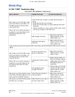
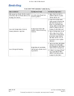
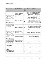
Страница 204: ...4 4 Check wiring to KSD 100EXP Circuit Breaker Not Set or Defective Check and or replace circuit breaker KSD 100EXP Defective Replace KSD 100EXP Smart Touch Not Working Touch Sensor Failure Reset KSD...

Страница 205: ...ed X AHRS Has Not Completed Initialization Wait for Attitude Aligning message to complete If on ground do not move aircraft while alignment is annunciated If in flight maintain straight and level flig...

Страница 206: ...peed failed See Altimeter Airspeed Failures troubleshooting procedure Any status parameters related to Ground Speed Track Angle Magnetic Variation True Airspeed and Magnetic Heading are invalid See No...

Страница 207: ...e performed RAM Memory Check Heartbeat Check APM Backup Check APM Module Check APM Module Data Check APM Backup Module and APM Module Mismatch Pilot Configuration NVM Memory Check Loopback Check FPGA...

Страница 208: ...LE DETECTION FAULT Displayed PBIT APM Module Detection Fault Loss of Communication with Configuration Module Check that Configura tion Module is installed and wired properly Configuration Module Defec...

Страница 209: ...iring from Autopilot to KSD 100EXP Reset KSD 100EXP If fault persists replace KSD 100EXP CBIT AFCS_CRS_ DEV _FLAG_OUT Loopback Fault Data Corrupted Reset KSD 100EXP If fault persists replace KSD 100EX...

Страница 210: ...owledge Screen refer to Figure 6 3 3 On the KSD 100EXP screen Figure 7 1 select the Menu button Figure 7 2 located at the top right of the screen 4 From the Main Menu Figure 7 6 select the System Tool...

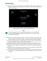
Страница 211: ...h point presented as a plus sign Figure 8 3 Example of Touch Calibration Utility Screen 9 When the user s touch is detected a bloom is displayed around the requested touch point 10 The touch point plu...

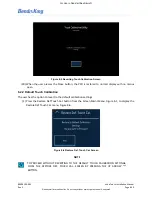
Страница 212: ...at random locations one after the other on the screen where the user should touch to test the precision of the Touch operation 15 Following the test button operation the Accept button is displayed at...

Страница 213: ...is restored to normal display with no menus open 8 2 2 Default Touch Calibration The user has the option to revert to the default calibration settings 1 Press the Restore Def Touch Cal button from the...

Страница 214: ...Restore Def Touch Cal menu the following screen Figure 8 7 is displayed indicating the successful restoration of the default values Figure 8 7 Restoration of Default Values Successful Screen 3 Press...

Страница 215: ...replace the KG 71EXP unit Note that because the CMT Application SW cannot communicate with the KG 71EXP there is no event logged After power up the KG 71EXP system does not provide any valid data all...

Страница 216: ...perature probe wiring including the KG 71EXP connector If there is no problem with wiring replace temperature probe If problem persists replace the KG 71EXP unit Note If temperature is out of the rang...

Страница 217: ...ck fails NA Restart the KG 71EXP If problem per sists replace the KG 71EXP unit Note that because of this failure Applica tion SW cannot start thus no event is logged Next the communication with the C...

Страница 218: ...e data and heading data during flight is reported HG 1120 CBIT detects a failure 7 Restart the KG 71EXP If problem per sists replace the KG 71EXP unit HG 1120 SPI Communication CBIT detects a failure...

Страница 219: ...more reliable Magnetometer availability CBIT detects a failure 14 Check the KMG 7010 MD32 wiring and circuit breaker including KMG 7010 MD32 and KG 71EXP connec tors If there is no issue with wiring r...

Страница 220: ...the magnetometer data readouts are significantly off from the required heading values there are the following probable sources 1 Ferrous bolts nuts were used to secure magnetometer or ferrous connecto...

Страница 221: ...or ALTITUDE FAIL Barometric altitude failure Use the standby altitude indicator VERTICAL SPEED FAIL Altitude rate failure or rate is out of range 5500 Use the standby vertical speed indicator GPS SOUR...

Страница 222: ...troubleshooting procedure in Table 8 1 xVue Touch System Troubleshooting Chart SVS POS Fault If any of the following inputs become invalid o Pressure Altitude o True Airspeed o Calibrated Airspeed See...

Страница 223: ...FAIL See No Navigation Data or Failure troubleshooting procedure in Table 8 1 xVue Touch System Troubleshooting Chart UAT FAIL Loss of Communication with UAT Check Wiring from UAT to KSD 100EXP Impro...

Страница 224: ...d database Re download failed database source content to USB drive and reload failed database If fault persists replace KSD 100EXP Database Tiles Corrupted During Run Time Reload failed database Re do...

Страница 225: ...ired prop erly Replace Configuration Module PILOT CONFIGURATION FAULT Pilot Stored Configuration Data Has Been Lost Replace KSD 100EXP APM MODULE CONFIGURATION DATA FAULT Configuration Module Defectiv...

Страница 226: ...off to allow it to cool down Check for adequate ventilation Check airflow around the KSD 100EXP for any blockages WARNING TERRAIN TERRAIN Warning during flight Comply with Warning WARING OBSTACLE OBS...

Страница 227: ...100EXP provides an alternative to the KSD 100EXP touch control capability for entering parameters such as altitude and barometric pressure course and heading The configuration module stores the confi...

Страница 228: ...tergent solution Dawn dish washing soap or similar and distilled water 1 Apply the water based detergent solution onto a clean lint free cotton cloth or cotton swab to clean the glass face 2 Carefully...

Страница 229: ...er to confirm that there is a maximum resistance of 2 5 milliohms or less between the unit and airframe ground If a resistance is found to be too high disassembly of the brackets will be required Chec...

Страница 230: ...ding straps or ground wires are in good condition and are not loose or chafing Connection points to the units and to the airframe must be inspected for evidence of corrosion If any of these indication...

Страница 231: ...osion If any of these indications are present an electrical bonding test must be performed 12 months KMG 7010 MD32 Magnetometer A general visual inspection of the KMG 7010 MD32 Magnetometer and the as...

Страница 232: ...chanical installation for condition including checking the unit and all mounting brackets for security Loose and chafing brackets will increase the resistance between parts Check for signs that the un...

Страница 233: ...es are in good condition and are not loose or chafing Connection points to the units and to the airframe must be inspected for evidence of corrosion If any of these indications are present an electric...

Страница 234: ...uch System components 9 2 6 Troubleshooting Refer to Section 8 of this document for troubleshooting steps The xVue Touch System components are not field repairable Repairs must be made by a properly c...

Страница 235: ...nector and remove the KTP 73 from the airplane 9 2 8 1 4 KG 71EXP Removal Execute the following steps for removal of the KG 71EXP 1 Ensure all power is removed from airplane 2 Disconnect the KG 71EXP...

Страница 236: ...2 3 Leak Test and Section 9 2 8 2 5 KMG 7010 Reinstallation For reinstallation of the KMG 7010 execute the steps in Section 4 6 KMG 7010 Installation as well as the steps in Section 6 3 KG 71EXP Confi...

Страница 237: ...e 9 11 Honeywell International Inc Do not copy without express permission of Honeywell For Use in Non Certified Aircraft 9 2 8 3 Return to Service Verify proper operation of the xVue Touch System by f...

Страница 238: ...llation Manual Rev 2 Page A 1 Honeywell International Inc Do not copy without express permission of Honeywell For Use in Non Certified Aircraft APPENDIX A OUTLINE AND INSTALLATION DRAWINGS Figure A 1...

Страница 239: ...002 xVue Touch Installation Manual Rev 2 Page A 2 Honeywell International Inc Do not copy without express permission of Honeywell For Use in Non Certified Aircraft Figure A 2 KSD 100EXP Panel Cutout D...

Страница 240: ...Installation Manual Rev 2 Page A 3 Honeywell International Inc Do not copy without express permission of Honeywell For Use in Non Certified Aircraft Figure A 3 KCP 100EXP Dimensions and Center of Grav...

Страница 241: ...nstallation Manual Rev 2 Page A 4 Honeywell International Inc Do not copy without express permission of Honeywell For Use in Non Certified Aircraft Figure A 4 KCP 100EXP Dimensions and Center of Gravi...

Страница 242: ...l International Inc Do not copy without express permission of Honeywell For Use in Non Certified Aircraft Figure A 5 KCP 100EXP Panel Cutout Dimensions NOTE UTILIZE SAME KCP 100EXP PANEL CUTOUT DIMENS...

Страница 243: ...xVue Touch Installation Manual Rev 2 Page A 6 Honeywell International Inc Do not copy without express permission of Honeywell For Use in Non Certified Aircraft Figure A 6 KG 71EXP Dimensions and Cente...

Страница 244: ...2 xVue Touch Installation Manual Rev 2 Page A 7 Honeywell International Inc Do not copy without express permission of Honeywell For Use in Non Certified Aircraft Figure A 7 KG 71EXP Mounting Hole Patt...

Страница 245: ...Touch Installation Manual Rev 2 Page A 8 Honeywell International Inc Do not copy without express permission of Honeywell For Use in Non Certified Aircraft Figure A 8 KMG 7010 Outline and Mounting Dra...

Страница 246: ...Touch Installation Manual Rev 2 Page A 9 Honeywell International Inc Do not copy without express permission of Honeywell For Use in Non Certified Aircraft Figure A 9 KMG 7010 Outline and Mounting Dra...

Страница 247: ...00109 002 xVue Touch Installation Manual Rev 2 Page A 10 Honeywell International Inc Do not copy without express permission of Honeywell For Use in Non Certified Aircraft Figure A 10 MD32 Outline Draw...

Страница 248: ...ouch Installation Manual Rev 2 Page A 11 Honeywell International Inc Do not copy without express permission of Honeywell For Use in Non Certified Aircraft Figure A 11 KDC 100EXP Outline and Mounting D...

Страница 249: ...ouch Installation Manual Rev 2 Page A 12 Honeywell International Inc Do not copy without express permission of Honeywell For Use in Non Certified Aircraft Figure A 12 KDC 100EXP Outline and Mounting D...

Страница 250: ...xVue Touch Installation Manual Rev 2 Page A 13 Honeywell International Inc Do not copy without express permission of Honeywell For Use in Non Certified Aircraft Figure A 13 KTP 73 Dimensions and Cente...

Страница 251: ...Rev 2 Page A 14 Honeywell International Inc Do not copy without express permission of Honeywell For Use in Non Certified Aircraft Figure A 14 KTP 73 Mounting Hole Pattern Figure A 15 KTP 73 Generic D...

Страница 252: ...tallation Manual Rev 2 Page B 1 Honeywell International Inc Do not copy without express permission of Honeywell For Use in Non Certified Aircraft APPENDIX B INTERCONNECT DIAGRAMS Figure B 1 xVue Touch...

Страница 253: ...3 D Z W d E E D Z ZK E E E s s Zd E s s d h E s E s hW E s D z E s K K K E Z W K K Z dhD Khd dhD Khd dhD Khd Z t y t D hdKW Kd KDWhd Z D Z Z E s s Zd E s s d E s E s hW E KDW s E K E Z E W E Z dhD dh...

Страница 254: ...Y Where XX is gauge and Y is color 2 Twisted Shielded Pair Triplet and Shielded Single Wire x All wires shall conform to ANSI NEMA WC 27500 x Do not remove any wiring between other active aircraft sys...

Страница 255: ...Zy W d Zy W D Zy W D Zy W D dy W D dy W D Zy W D Zy W D dy W D dy W Z E W Z dy E W Z dy E W Z E sKZ dy sKZ dy sKZ Zy sKZ Zy sKZ Zy sKZ Zy sKZ dy sKZ dy KtE E hW E KtE E hW E d d d d E E E E Z h Z h Z...

Страница 256: ...31 29 T 17 14 15 16 T 17 32 43 31 32 33 1 1 NOTES 1 Twisted Shielded Pair Triplet and Shielded Single Wire x All wires shall conform to ANSI NEMA WC 27500 x Do not remove any wiring between other acti...

Страница 257: ..._15VDC KSD100_CTRL_PANEL_PWR_RTN 9 8 15VDC_PWR_IN 15VDC_PWR_RTN 5 NOTES 1 Single Conductor Wire x All wires shall be 22 AWG unless otherwise noted power wires x Wiring shall meet AS22759 16 XX Y Where...

Страница 258: ...nc Do not copy without express permission of Honeywell For Use in Non Certified Aircraft Figure B 7 KG 71 LRU Interconnect Diagram 1 yW d DW WZK d DW WZK d DW WZK Z t dW d DW d DW d DW yW E E D E h E...

Страница 259: ...002 xVue Touch Installation Manual Rev 2 Page B 8 Honeywell International Inc Do not copy without express permission of Honeywell For Use in Non Certified Aircraft Figure B 8 KG 71 LRU Interconnect D...

Страница 260: ...express permission of Honeywell For Use in Non Certified Aircraft Figure B 9 KG 71 LRU Interconnect Diagram 3 E t yW dy dy Zy Zy E t E t W t W t dE dE dE dE dE E E EKd t x t x t yy z t yy z d W d t x...

Страница 261: ...not copy without express permission of Honeywell For Use in Non Certified Aircraft Figure B 10 KG 71 LRU Interconnect Diagram 4 yW Z dy d Z d E EKd t x t x t yy z t yy z d W d t x E E D t x d D yW dy...

Страница 262: ..._______________________________ Table C 1 xVue Touch System Component Locations Description PN Airplane Location Access Panels KSD 100EXP PFD 89000120 001 KCP 100EXP Control Panel Portrait KCP 100EXP...

Страница 263: ...l International Inc Do not copy without express permission of Honeywell For Use in Non Certified Aircraft On Figure C 1 draw in the location of the xVue Touch System components and the wiring routing...

Страница 264: ...Non Certified Aircraft On Figure C 2 draw in the location of the xVue Touch System components and the wiring routing Figure C 2 xVue Touch System Components and Cable Routing Side View On Figure C 3 d...

Страница 265: ...Power Source Capacity Analysis and confirm the aircraft electrical system is capable of supporting the xVue Touch System Refer to Section 4 12 for additional information Table C 2 Electrical Load Anal...

Страница 266: ...nal Inc Do not copy without express permission of Honeywell For Use in Non Certified Aircraft APPENDIX D MD32 INSTALLATION MANUAL For instructions on how to install the MD32 Magnetometer see the Insta...

Страница 267: ...structions Model MD32 Series Remote Magnetometer Mid Continent Instrument Co Inc dba Mid Continent Instruments and Avionics 9400 E 34th Street N Wichita KS 67226 Manual Number 9019050 PH 800 821 1212...

Страница 268: ...mcico com We welcome your comments concerning this manual Although every effort has been made to keep it free of errors some may occur When reporting a specific problem please describe it briefly and...

Страница 269: ...ided additional details in 2 4 regarding limitations and deviations 2 Added description for wire shield terminations 3 Updated Environmental Qualification Statement in 3 2 4 Removed reference to EASA...

Страница 270: ...Performance Limits 6 Qualifications 6 SECTION 2 INSTALLATION 7 2 1 GENERAL INFORMATION 7 2 2 PARTS LIST 7 2 3 EQUIPMENT LOCATION 7 2 4 LIMITATIONS 7 2 5 MODIFICATIONS 8 2 6 CABLE HARNESS 9 Wire Gauge...

Страница 271: ...e 4 wire shielded cable connecting data and power to the MD302 As an added benefit the backup battery integral to the MD302 is also capable of supporting the MD32 Remote Magnetometer in the case of ai...

Страница 272: ...inches x 0 81 inches LxWxH Mating Connector MCI P N 8017287 Mounting Base mount any orientation Table 1 2 Performance Limits Heading Accuracy vs Latitude Within 2 up to 55 N or 45 S increasing error t...

Страница 273: ...incomplete system It must be installed in conjunction with an MD302 Standby Attitude Module MCIA part number 6420302 to provide complete heading functionality The MD302 must have software version 1 1...

Страница 274: ...r 6420032 has a nameplate that identifies the manufacturer part number description certifications and technical specifications of the unit It also includes the MOD or modification number representing...

Страница 275: ...make a tee connection to Pin 1 of the MD302 Another option is to connect to Pin 11 of a MOD 2 MD302 for backup power from the internal battery Pin 6 ARINC Out B connects to MD302 Pin 13 Optionally it...

Страница 276: ...Rev C March 30 2018 10 Manual Number 9019050 Figure 2 1 MD32 Outline Drawing...

Страница 277: ...nued airworthiness of the MD32 Remote Magnetometer If the unit fails to perform to specifications or if the magnetic environment of the aircraft installation changes over time recalibration may be per...

Страница 278: ...ash Safety 7 Category B Vibration 8 Category R Curves E E1 REE1 Explosion 9 Category X Waterproofness 10 Category W Fluids 11 Category X Sand and Dust 12 Category X Fungus 13 Category X Salt Fog 14 Ca...

Страница 279: ...Honeywell International Inc Do not copy without express permission of Honeywell...

Страница 280: ...umber of Reviewers 1 Finished 1 Not Finished 0 Approver Progress Approver Name Title Percent Complete Approval Date Signature Signature Comments Dustin J Sinko Engineer Pr Systems 100 November 1 2019...

Отзывы: