89000109-002
xVue Touch Installation Manual
Rev 2
Page 4-23
© Honeywell International Inc. Do not copy without express permission of Honeywell.
For Use in Non-Certified Aircraft
4.12 Aircraft Electrical Load Analysis (ELA)
An Electrical Load Analysis (ELA) must be completed to confirm that the airplane electrical system is
capable of supporting the xVue Touch System. For airplanes in the normal, utility and acrobatic category
this ELA can be by analysis or by measurements; the ELA accounts for the electrical loads applied to the
electrical system in probable combination and for probable durations.
Airplanes with an existing ELA shall use Section 4.12.1, and airplanes without an ELA may perform either
Section 4.12.3 or Section 4.12.2.
4.12.1 Aircraft with Existing ELA
If the airplane has an existing ELA, update the ELA to reflect the addition of the xVue Touch System. The
updated ELA must show the alternator/generator has adequate capacity to supply power to the modified
systems in all anticipated conditions. The typical current draw for the xVue Touch System is provided in
Table 4-4 and should be added to the existing ELA under continuous operating conditions. Verify the new
electrical load does not exceed 80% of the alternator/generator data plate rated capacity or the
maximum load value (if published in the Airplane Flight Manual). In addition, in the event of a complete
loss of the primary electrical system the battery(s) must be capable of providing at least 30 minutes of
electrical power to those loads that are essential to continued safe flight and landing.
4.12.2 Aircraft without an Existing ELA - Measurement Method
An acceptable method of performing an ELA is to determine the electrical loads by measurement. The
measured electrical loads must include all the probable combinations and durations expected during
normal aircraft operation. Verify the maximum electrical demand does not exceed 80% of the alternator/
generator data plate rated capacity or the maximum load value (if published in the Airplane Flight
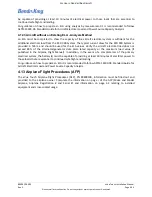
Manual). In addition, in the event of a complete loss of the primary electrical system the battery(s) must
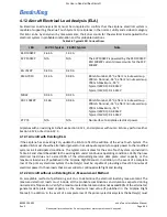
Table 4-4 Typical LRU Current Draw
LRU
14 VDC Typical
28 VDC Typical
Note
KSD 100EXP
2.66 A
1.33 A
KCP 100EXP
N/A
N/A
The KCP 100EXP is powered by the KSD 100EXP.
KSD 100EXP current draw accounts for the KCP
100EXP.
KG 71EXP
0.40 A
0.20 A
KMG 7010
0.16 A
0.08 A
80 mA Nominal, 25°C, after 2 minute warmup
200 mA Nominal, -55°C, after 2 minute warmup
700 mA Maximum, -55°C
Typical (28VDC): 0.08 AMP
Typical (14VDC): 0.16 AMP
MD32
0.04 A
0.02 A
KDC 100EXP
0.16A
0.08 A
80 mA Nominal, 25°C, after 2 minute warmup
200 mA Nominal, -55°C, after 2 minute warmup
700 mA Maximum, -55°C
Typical (28VDC): 0.08 AMP
Typical (14VDC): 0.16 AMP
KTP 73
N/A
N/A
No interface to airplane electrical power.

