


BendixKing
AeroPanel 100 Audio Selector Panel
Installation and Operator’s Manual
89000063-011
Page 3-2
Rev. 0, April 2020
When switching from C
OM
1 to C
OM
2 while Com 2 was not previously selected, C
OM
1 audio will be
switched off. In essence, switching the mic selector will not override prior selection of COM receiver audio.
In normal (not split) modes, the AeroPanel 100 gives priority to the pilot’s radio Push-To-Talk (PTT). If the
copilot it transmitting, and the pilot presses his PTT, the pilot’s microphone will be heard over the selected
com transmitter.
If the pilot microphone and headphones are connected to the cell phone, the pilot PTT will switch the pilot
microphone to the selected com transceiver, and allow continued aircraft communications to continue.
The copilot will also be able to transmit on the other selected radio with his PTT as well.
3.2.1.1
Split Mode
The split mode can be activated at any time by pressing the
XMT
1
and
XMT
2
buttons at the same time.
This places the pilot on C
OM
1 and the Copilot on C
OM
2.
Pilot on C
OM
2 and Copilot on C
OM
1 is not possible.
N O T E
Due to the nature of VHF communications signals, and the size constraints in general aviation aircraft, it is
probable that there will be some bleed-over in the Split mode, particularly on adjacent frequencies.
BendixKing makes no warranty about the suitability of Split Mode in all aircraft conditions.
When the split mode is activated, the intercom between the pilot and copilot is inhibited, although the pas-
sengers can still talk among themselves. The crew intercom can be reactivated if desired by pressing the
“Mute” button. The indicator LED in the Mute button will be green when the intercom is off (muted), and
turn off to indicate that the intercom is not muted, and the crew can speak to each other.
3.2.1.2
Swap Mode (Switch from Com 1 to Com 2 remotely) Remote intercom mode control
With a yoke mounted, normally open momentary switch, the pilot can change from the current Com trans-
ceiver to the other by depressing this switch. To cancel "Swap Mode," the pilot may either press the yoke
mounted switch again, or select a different Com with the XMT buttons.
The panel- or yoke-mounted optional “swap” switch can also act as a remote intercom mode. A long (>1
second) press of the swap switch will increment the intercom mode selector from ISO-ALL-CRW-ISO, etc.
each time the button is pressed and held.
3.2.1.3
IntelliAudio® Head related Transfer Function (HRTF)(11)
The IntelliAudio feature will place COM 1 in the apparent 10 o’clock position to the flight crew’s headset,
and COM 2 in the apparent 2 o’clock position.
This feature is turned on and off by pressing the HRTF button.
NOTE: IntelliAudio requires stereo headsets in pilot and copilot locations with correctly oriented left and
right ear cups.
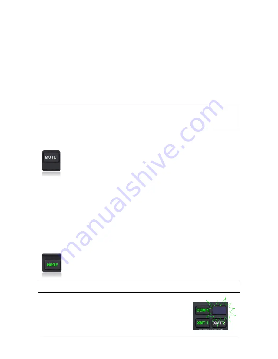
3.2.1.4
Monitor Mode
The Monitor Mode causes the audio from a primary radio (selected for transmit)
mute the secondary radio (selected for listen only) when the primary radio is re-
ceiving a signal. This allows the crew to copy weather but still hear ATC clearly.
Press the COM button on secondary radio until “Monitor ON” is heard in the
headset to activate the Monitor mode. The secondary COM button will blink in
COM 2


