background image

9

4.

If the work is being performed on the vehicle’s air
brake system, or any auxiliary pressurized air
systems, make certain to drain the air pressure from
all reservoirs before beginning ANY work on the
vehicle.  If the vehicle is equipped with an AD-IS

air dryer system or a dryer reservoir module, be
sure to drain the purge reservoir.

5.

Following the vehicle manufacturer’s
recommended procedures, deactivate the electrical
system in a manner that safely removes all
electrical power from the vehicle.

6.

Never exceed manufacturer’s recommended
pressures.

7.

Never connect or disconnect a hose or line
containing pressure; it may whip. Never remove a
component or plug unless you are certain all
system pressure has been depleted.

8.

Use only genuine Bendix

®

 replacement parts,

components and kits. Replacement hardware,
tubing, hose, fittings, etc. must be of equivalent
size, type and strength as original equipment and
be designed specifically for such applications and
systems.

9.

Components with stripped threads or damaged
parts should be replaced rather than repaired.  Do
not attempt repairs requiring machining or welding
unless specifically stated and approved by the
vehicle and component manufacturer.

10. Prior to returning the vehicle to service, make

certain all components and systems are restored
to their proper operating condition.

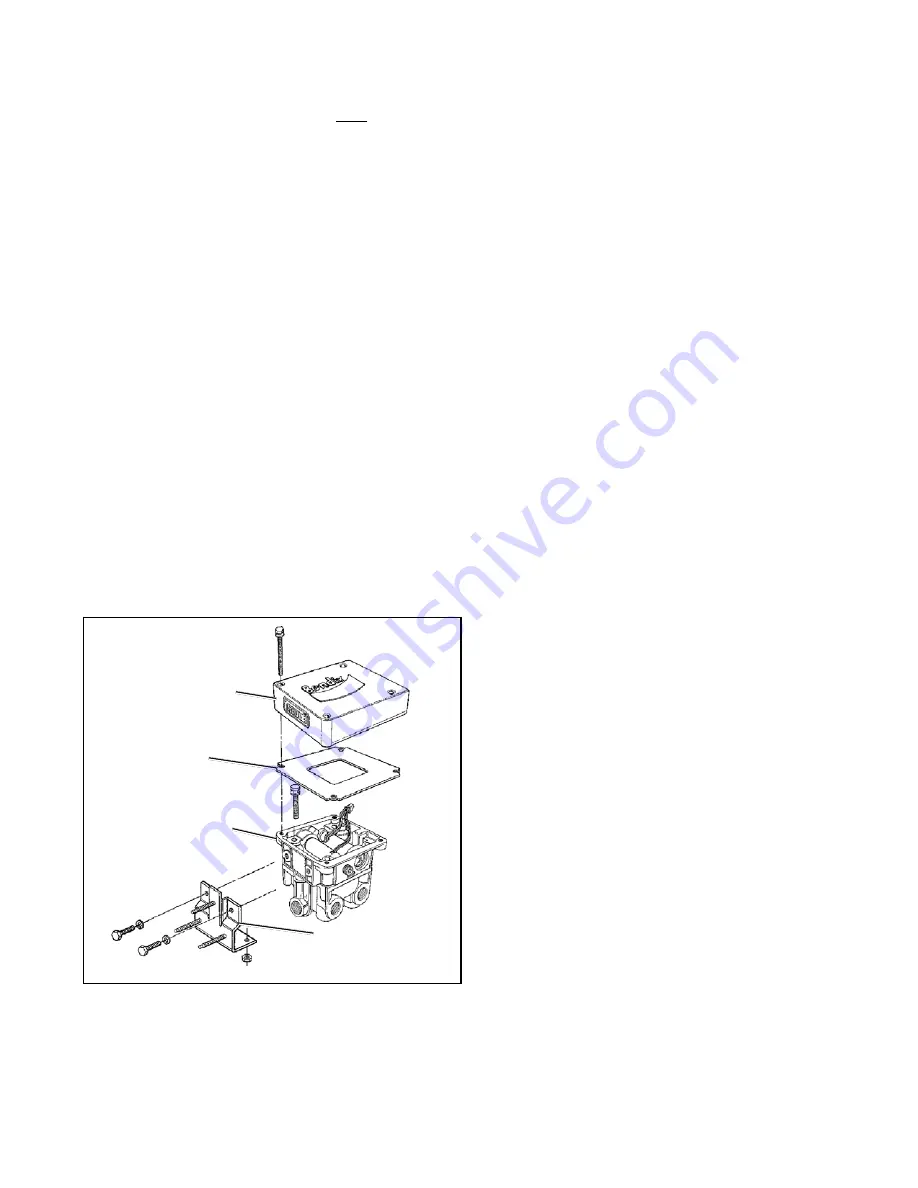
REMOVING EC-14

 CONTROLLER ASSEMBLY

Locate the EC-14

 controller on the trailer and determine if

it is mounted on a modulator (e.g. M-12

 modulator) or is

remote mounted to a trailer frame member using a bracket.
Use the appropriate removal procedure below.

Removing the EC-14

 Controller and M-12

 Modulator:

1. Identify and remove all air lines connected to the

M-12

 modulator.

2. Disconnect the electrical connector from the EC-14

controller.

3. Note and mark the mounting position of the MC-14

modulator-controller assembly on the vehicle. Loosen,
remove and save the nuts on the mounting hardware
that attaches the MC-14

 modulator controller bracket

to the vehicle. Remove the MC-14

 modulator controller

assembly from the vehicle.

4. Remove as much contamination as possible from the

exterior of the assembly making sure to keep the
contamination away from the open ports.

5. Note and mark the position of the EC-14

 controller

relative to the M-12

 modulator. Remove and retain the

four hex cap screws that secure the EC-14

 controller

to the M-12

 modulator. Carefully separate the EC-14

controller from the M-12

 modulator enough to expose

the wire harness that connects both units electrically.
Disconnect the wire harness by separating the four pin
connector at the EC-14

 controller. Peel the gasket from

the EC-14

 controller or M-12

 modulator and retain for

reuse.  Note: Use a new gasket if damaged during
removal or if a new gasket is immediately available.

INSTALLING THE EC-14

 CONTROLLER

ASSEMBLY

1. After noting the positioning marks made prior to

disassembly, reconnect the M-12

 modulator wire

harness to the EC-14

 controller, position the gasket

on the EC-14

 controller then secure the EC-14

controller to the M-12

 modulator using the four cap

screws. Torque the cap screws to 50-80 Ibs. in.

2. Mount the assembled MC-14

 modulator controller on

the vehicle and orient it in the position marked prior to
removal.

3. Reconnect all air lines.

4. Reconnect the electrical connector to the EC-14

controller.

5. Test the MC-14

 modulator controller for operation and

air leakage prior to placing the vehicle in service.

6. Perform the “Initial Start up Procedure” in the

Troubleshooting  section to assure proper antilock
system operation.

DIAGNOSING AND LOCATING A SYSTEM
PROBLEM

GENERAL

The EC-14

 controller contains self test and diagnostic

circuitry that continuously checks for proper operation of

FIGURE 7 - MC-14

 MODULATOR CONTROLLER

EC-14

CONTROLLER

GASKET

MOUNTING

BRACKET

M-12

MODULATOR

Содержание EC-14 ANTILOCK CONTROLLER

Страница 1: ...system are contained in a die cast aluminum housing and are environmentally protected by silicone encapsulation The metal housing coupled with the design of the digital electronics is intended to pro...

Страница 2: ...2 FIGURE 2 MC 14 ANTILOCK BRAKE SYSTEM...

Страница 3: ...l speed information from various wheel speed sensor models at the rate of 100 pulses per wheel revolution The EC 14 controller is able to simultaneously receive and individually interpret speed signal...

Страница 4: ...ONNECTOR DEUTSCH 2 PIN CONNECTOR 90 WS 20 WHEEL SPEED SENSOR STRAIGHT WS 20 WHEEL SPEED SENSOR BRAKE DRUM SPEED SENSOR MOUNTING BLOCK 100 TOOTH SPEED SENSOR EXCITER RING WS 20 WHEEL SPEED SENSOR 90 DE...

Страница 5: ...eans of advising the driver of the condition of the antilock system A connection to the Engine or Transmission Retarder is provided on the EC 14 controller which allows the EC 14 controller to tempora...

Страница 6: ...NON ANTILOCK BRAKE APPLICATION During normal braking the brake valve simultaneously delivers air to the control port of the M 12 modulator on the rear axle s as well as to and through the M 21 or M 22...

Страница 7: ...rformed during this period Because no two vehicles operate under identical conditions maintenance and maintenance intervals will vary Experience is a valuable guide in determining the best maintenance...

Страница 8: ...8 FIGURE 6 MC 14 ANTILOCK WIRING SCHEMATIC...

Страница 9: ...tion of the MC 14 modulator controller assembly on the vehicle Loosen remove and save the nuts on the mounting hardware that attaches the MC 14 modulator controller bracket to the vehicle Remove the M...

Страница 10: ...DS There are nine LEDs plus a magnetically actuated reset switch in the EC 14 controller diagnostic window The first five LEDs locate a problem to a specific area of the trailer while the last four in...

Страница 11: ...during vehicle operation to indicate that vehicle power is reaching the controller If vehicle power is out of range for proper operation below 10 vdc or above 17 vdc this LED will flash until power is...

Страница 12: ...odulators Go to Section I Dash Lamp Testing YES YES NO Dash lamp remains on NO Go to Section III Inspection for illuminated LEDs YES NO The system is functioning normally Make notes of the parts repla...

Страница 13: ...on on measure voltage between lamp relay Pin 3F and ground Pins 1A 2A Voltage should be same as battery voltage Replace the EC 14 controller Go to Section II Inspection for Illuminated LEDs Check wiri...

Страница 14: ...nspection for Illuminated LEDs NO Record the condition of all red LEDs Go to Section IX Testing for False Failure Indication Caused by Dash Lamp Relay NO Go to Section V Testing for Power to the EC 14...

Страница 15: ...lluminated Go to Section IV Inspection for Illuminated LEDs Record the condition of all red LEDs Go to Section X Testing For False Failure Indication Caused by Wheel Speed Components NO Go to Section...

Страница 16: ...NO Is the red FRONT or REAR LED illuminated See Note 1 below Is the red FRONT or REAR LED illuminated See Note 1 below NO YES REAR LED FRONT LED Go to Section VII Testing the Rear Modulator ON ON ON...

Страница 17: ...een power and ground pins on wire harness connector 1A to 1K 1A to 2K 2A to 1 K 2A to 2 K Reconnect connector to EC 14 controller Check the vehicle wiring for continuity Refer to the vehicle service m...

Страница 18: ...o Power 2F to 1K 2K No Continuity Exhaust to Ground 2F to 1A 2A No Continuity NO Go to Section VI B and continue testing Are resistance values correct 1A 2A GROUND 2F EXHAUST 2G HOLD 1K 2K POWER 1G SO...

Страница 19: ...Test each pin to vehicle ground and note no continuity Are resistance values correct Replace the front M 21 modulator NO Reconnect connector to modulator Turn ignition on and pass magnet over RESET o...

Страница 20: ...NET HERE YES STARTHERE Turn the ignition off Separate the EC 14 controller from the M 12 modulator Disconnect the four pin connector between the two components and test resistance on the modulator con...

Страница 21: ...If sensor gap must be adjusted check for loose or worn wheel bearings before re gapping sensor Refer to vehicle maintenance manual for worn bearings C If sensor gap is correct check wheel bearing for...

Страница 22: ...esistance between two pins on sensor Is resistance between 1500 2500 Ohms for the Bendix WS 20 speed sensor NO Replace the sensor YES NO Reconnect connector at speed sensor and EC 14 controller Pass m...

Страница 23: ...mation Repair or replace as necessary and repeat the Initial Start up Procedure Repeat the Initial Start up Procedure If testing has returned to this step twice replace the EC 14 controller and retest...

Страница 24: ...onds or more Bring vehicle to a stop and turn off ignition Turn the ignition off Refer to Section VII Part A Testing the wheel sensor and perform tests and inspections B through F in the large box Rep...

Отзывы: