26
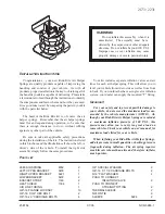
FIGURE 55 -
INSTALLING ADJUSTING SCREW LOCK NUT
31. Lightly lubricate the seals(29) contained in both the
housing (22) and side cover(31) with lithium grease.
Lubricate the sealing surface of the output shaft (25)
on the adjusting screw end only. Using a 7mm socket
wrench install the assembled side cover (31) on the
output shaft adjuster screw (33) and screw it on as far
as it will go, then back it off 1/8 of a turn. Figure 54
32. Prior to inserting the assembled side cover and output
shaft (25) into the housing (22), wrap a single layer of
masking tape around the splines to protect the housing
seal (29). Lubricate the exterior of the tape with a lithium
grease and insert the shaft and side cover assembly
into the housing with a twisting motion. Remove the
masking tape from the output shaft splines. Figure 54
33. Secure the side cover to the housing using four bolts
(49). Make certain that the side cover is positioned so
that the marks made during disassembly are aligned.
Torque the bolts to between 81 and 88 pound feet for
the C-300N and 92-99 pound feet for the C-500N, using
a 19mm socket and torque wrench. Pack the cavity of
exterior dust boot (39) with high temperature grease
provided in the Bendix maintenance kit, then install the
exterior dust boot (39) on the output shaft. Refer to
Figures
13 & 16
PRELOAD ADJUSTMENT
ADJUSTING THE PISTON TO OUTPUT SHAFT
GEAR PRELOAD
34. The piston and output shaft gear preload is correct when
a 4 to 18 pound-inch
increase
in torque is noted at the
input shaft as it is rotated and the piston passes through
the midpoint of its total travel in the housing. The torque
increase at the input shaft will occur only as the piston
travels through the mid point of its travel and should
disappear as the piston moves past the midpoint.
To obtain the adjustment stated above, make certain the
adjusting screw (33) is turned counterclockwise as far
as it will go. Rotate the input shaft as far as possible in
both directions. Count the total revolutions in either
direction and at the same time measure the average
torque to rotate the shaft.
To obtain the proper preload adjustment, rotate the input
shaft 180° in both directions past the midpoint of piston
travel. (The midpoint of piston travel is
approximately
one half the number of input shaft revolutions possible
in a single direction.)
Each time the direction of input shaft rotation is changed,
turn the output shaft adjustment screw (33) clockwise
1/8 to 1/4 turn. Continue this procedure until a 4 to 18
pound inch
increase
is noted in the torque required to
rotate the input shaft.
35. When the adjustment is correct, install lock nut (33)
and apply a torque of 74 to 88 pound feet with a 19mm
crow foot and torque wrench while holding the
adjustment screw in position with the 7mm socket and
torque wrench.
Figure
55
36. After all the described steps have been performed, check
that the power steering unit runs smoothly throughout
its entire motion and that the gear preload at the center
position is as prescribed in Step 34.
37. Install the power steering gear on the vehicle. Fill gear
with fluid per vehicle manufacturers procedure. Test
for flow, leakage and the pressure relief valve setting (if
applicable) as well as setting the stroke limiting (if
applicable).
STEERING LIMITING STEM ADJUSTMENT
GENERAL
The function of the optional steering limiting feature is
to relieve most of the hydraulic power assist prior to the
piston (23) reaching the end of its full travel in either
direction. This ensures that the axle stops are not
impacted with full hydraulic assist when a full wheel cut
is made in either direction.
The C-300N has two adjustable steering limiting stems
(13 & 19) of which only one (19) is externally adjustable.
The internal adjustable stem (13) must be preset during
assembly to meet vehicle requirements.
The C-500N has two externally adjustable steering limiting
stems (19), one located in the housing (22) (like the
C-300N) and one in the valve body (7). Both stems are
adjusted externally after mounting the C-500N on the
vehicle.
The following instructions are for the externally adjustable
steering limiting stem.


