background image

21

isoUG425_D00220_00_Q_DEEN / 04.2016

4.  Installation and connection

Consider a minimum distance to adjacent devices: 
sides 0 mm; above and below 20 mm.

DIN rail mounting

Snap the mounting clip at the rear of the device onto the DIN rail so that it sits 
so that it sits securely

Screw mounting

Use a tool to position the rear mounting clips (a second mounting clip is requi-
red, see ordering information in the manual) so that it protrudes over the
enclosure. Fix the device with two M4 screws (see below).

Risk of electric shock!

Avoid any physical contact with active conductors and
ensure compliance with the regulations for working on
electrical installations

.

DANGER

90 mm

45

67.5

36 mm

31.1

47.5

70.5

2

2

1

2

3

Click

Содержание ISOMETER isoUG425

Страница 1: ... Hauptstromkreisen IT Systemen mit Netznennspannun gen von DC 12 120 V Die maximal zulässige Netzableitkapazität Ce beträgt 50 μF Die bei einem Isolationsfehler eines Netzleiters gemessene Verlagerungsspannung wird messtechnisch ausgewertet Durch das passive Messverfahren können nur unsymmetrische Isolationsfehler erfasst werden Gleich große Isolationsfehler von der Plus und Minusleitung gegen Erd...

Страница 2: ...sprechwerte des Menüs AL erfolgt eine Meldung über die LEDs sowie die Relais K1 und K2 gemäß den Einstellungen in der Meldezu ordnung im Menü out Dort kann auch die Arbeitsweise der Relais n o n c eingestellt sowie der Fehlerspeicher M aktiviert werden Verletzen die Werte RF oder Un ihren jeweiligen Rückfallwert Ansprechwert zuzüglich Hysterese ununterbrochen nicht mehr für die Dauer toff schalten...

Страница 3: ... gewährleistet ist Schraubbefestigung Bringen Sie die rückseitigen Montageclips 2 Montageclip erforderlich siehe Bestellinformation mittels Werkzeug in eine über das Gehäuse hinaus ragen de Position Befestigen Sie das Gerät mit zwei M4 Schrauben Gefahr eines elektrischen Schlages Sorgen Sie für Spannungsfreiheit im Montage bereich und beachten Sie die Regeln für das Arbei ten an elektrischen Anlag...

Страница 4: ...0 430 auf Schutzeinrichtungen zum Schutz bei Kurzschluss verzichtet werden wenn die Leitung oder das Kabel so ausgeführt ist dass die Gefahr eines Kurz schlusses auf ein Mindestmaß beschränkt ist Mit einer externen Test Reset Taste darf nur ein ISOMETER angesteuert werden Eine galvanische Parallelschaltung mehrerer Test oder Reset Eingänge für Sammelprüfungen von ISOMETER n ist nicht erlaubt L KE ...

Страница 5: ...jeweils separat an PE anschließen Gleichen Leitungsquerschnitt wie bei A1 A2 verwenden L L Anschluss an das zu überwachende DC Netz T R Anschluss für externe kombinierte Test und Reset Taste 11 14 Anschluss Alarmrelais K1 11 24 Anschluss Alarmrelais K2 A B RS 485 Kommunikationsschnittstelle mit zuschaltbarem Terminierungswiderstand Fehlercode Bedeutung E 01 Die Verbindung der Anschlüsse E oder KE ...

Страница 6: ... Isolationswiderstand C Ableitkapazität 2 Überwachter Leiter 3 Spannungsart DC Spannungsart RMS 4 Messwerte und Einheiten 5 Passwortschutz ist aktiviert 6 Im Menübetrieb wird die Arbeitsweise des jeweiligen Alarmrelais angezeigt 7 Kommunikationsschnittstelle mit Messwert isoData Betrieb 8 Fehlerspeicher ist aktiviert 9 Zustandssymbole 10 Kennung für Ansprechwerte und Ansprechwertverletzung ON AL1 ...

Страница 7: ...en und löschen ESC Zur nächsthöheren Menüebene bewegen Enter oder t 5 Min k R Standardanzeige R kΩ U L1 L2 VRMS U L1 L2 VDC UL1 VDC UL2 VDC Messwertanzeige Menü Esc Menüauswahl AL out t SEt InF HiS ESC Enter Esc Parameterauswahl P1 Pn ESC Optionales Passwort Parameter editieren Parameter speichern Enter Enter Enter Esc Funktion Taste Betätigung Enter Menü Esc Test Reset Auswahl Eingabe bestätigen ...

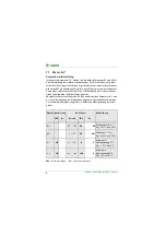
Страница 8: ...er R2 zuzüglich des Hysteresewertes siehe Tabelle unten wird der Alarm gelöscht Ebenfalls im Ansprechwertmenü AL können die beiden Parameter U und U zur Überwachung der Netzspannung aktiviert bzw deaktiviert werden Der maximale Unterspannungswert ist durch den Überspannungswert be grenzt FAC Werkseinstellung Ke Kundeneinstellungen Display Aktivierung Einstellwert Beschreibung FAC Ke Bereich FAC Ke...

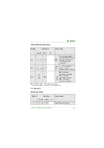
Страница 9: ... rekt den Meldungen zugeordnet und hat keinen Bezug zu den Relais Kann das Gerät einen unsymmetrischen Isolationsfehler dem entsprechen den Leiter L oder L zuordnen setzt es nur die jeweilige Meldung Relais K1 Relais K2 Beschreibung Display FAC Ke Display FAC Ke n c n c Arbeitsweise Relais n c n o K1 r1 K2 r2 LEDs Meldungs beschreibung Display FAC Ke Display FAC Ke ON AL1 AL2 off on Gerätefehler E...

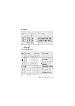
Страница 10: ...ehler RF an L r1 R2 Ω off r2 R2 Ω on Alarm R2 Fehler RF an L r1 U V off r2 U V on Alarm UnDC Unterspannung r1 U V off r2 U V on Alarm UnDC Überspannung r1 test off r2 test off Manuell gestarteter Gerätetest r1 S AL off r2 S AL off Gerätestart mit Alarm Display FAC Ke Beschreibung M off Memoryfunktion für Alarmmeldungen Fehlerspeicher K1 r1 K2 r2 LEDs Meldungs beschreibung Display FAC Ke Display FA...

Страница 11: ...FAC Ke Adr 0 3 90 3 Bus Adr Adr 0 deaktiviert BMS sowie Modbus und aktiviert isoData mit kontinuierli cher Datenausgabe 115k2 8E1 Adr 1 1 2k 115k Baud rate BMS Bus 9k6 7E1 1 2k 115k Modbus variabel variabel Adr 2 8E1 8o1 8n1 8E1 Modbus 8E1 8 Datenbits even Parity 1 Stoppbit 8o1 8 Datenbits odd Parity 1 Stoppbit 8n1 8 Datenbits no Parity 1 Stoppbit Display Einstellwert Beschreibung Bereich FAC Ke t...

Страница 12: ...off 0 99 0 s Rückfallverzögerung K1 und K2 test OFF 1 24 24 h Wiederholzeit Gerätetest Display Aktivierung Einstellwert Beschreibung FAC Ke Bereich FAC Ke off 0 999 0 Passwort für Parametereinstellung C 1 50 1 μF Maximal zulässige Ableit kapazität Ce S Ct on Gerätetest bei Gerätestart FAC Werkseinstellung Factory Setting ausführen SYS Nur für Bender Service Display Einstellwert Beschreibung Bereic...

Страница 13: ...prechwert erreicht oder ver letzt bzw der Messbereich unter oder überschritten wurde Messwert kann im Historienspeicher angezeigt werden HiS Display Beschreibung R kΩ Isolationswiderstand RF 1 kΩ 1 MΩ Auflösung 1 kΩ U L1 L2 V Netzspannung L L UnRMS 0 VRMS 99 9 VRMS Auflösung 0 1 VRMS 100 VRMS 150 VRMS Auflösung 1 VRMS U L1 L2 V Netzspannung L L UnDC 0 VDC 99 9 VDC Auflösung 0 1 VDC 100 VDC 150 VDC...

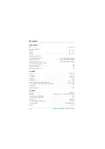
Страница 14: ...fungen nach IEC 61010 1 2 2 kV Versorgungsspannung Versorgungsspannung Us AC 100 240 V DC 24 240 V Toleranz vonUs 30 15 FrequenzbereichUs 47 63 Hz Eigenverbrauch 3 W 9 VA Überwachtes IT System Netznennspannung Un DC 12 120 V Toleranz vonUn 20 Messkreis InnenwiderstandRi 115 kΩ Zulässige Netzableitkapazität Ce 50 μF Ansprechwerte Ansprechwert Ran1 2 100 kΩ 50 kΩ Ansprechwert Ran2 1 95 kΩ 25 kΩ Ansp...

Страница 15: ... off Fehlerspeicher Alarmmeldungen on off Schnittstelle Schnittstelle Protokoll RS 485 BMS ModbusRTU isoData Baudrate BMS 9 6 kBit s Modbus RTU einstellbar isoData 115 2 kBits s Leitungslänge 9 6 kBits s 1200 m Leitung paarweise verdrillt Schirm einseitig an PE min J Y St Y 2x0 6 Abschlusswiderstand 120 Ω 0 25 W intern zuschaltbar Geräteadresse BMS Bus Modbus RTU 3 90 3 Schaltglieder Schaltglieder...

Страница 16: ...3 2 2M2 Langzeitlagerung IEC 60721 3 1 1M3 Anschluss Anschlussart Federklemme Nennstrom 10 A Leitergrößen AWG 24 14 Abisolierlänge 10 mm starr flexibel 0 2 2 5 mm2 flexibel mit Aderendhülse mit ohne Kunststoffhülse 0 25 2 5 mm2 Mehrleiter flexibel mit TWIN Aderendhülse mit Kunststoffhülse 0 5 1 5 mm2 Öffnungskraft 50 N Testöffnung Durchmesser 2 1 mm Sonstiges Betriebsart Dauerbetrieb Einbaulage Kü...

Страница 17: ...17 isoUG425_D00220_00_Q_DEEN 04 2016 Bestellangaben Typ Ausführung Art Nr isoUG425 D4 4 Federklemme B 7103 6320 Montageclip für Schraubmontage 1 Stück je Gerät B 9806 0008 ...

Страница 18: ......

Страница 19: ...cuits IT systems with mains voltages of DC 12 120 V The maxi mum permissible system leakage capacitance Ce is 50 uF In the case of an insulation fault on a power conductor the measured residual voltage is evaluated to determine the insulation resistance RF Only asymmetrical insulation faults can be detected using the passive measurement method employed in this ISOMETER Equally large insulation fau...

Страница 20: ...xceed the thresholds set in the AL menu this will be indicated by the LEDs and re lays K1 and K2 according to the message assignment settings in the out me nu In addition the operation of the relay n o n c can be set and the fault memory M activated If the values of RF or Un exceed their release value re sponse value plus hysteresis without interruption for a period no longer than toff then the al...

Страница 21: ...hat it sits securely Screw mounting Use a tool to position the rear mounting clips a second mounting clip is requi red see ordering information in the manual so that it protrudes over the enclosure Fix the device with two M4 screws see below Risk of electric shock Avoid any physical contact with active conductors and ensure compliance with the regulations for working on electrical installations DA...

Страница 22: ... for the coupling of terminals L L to the IT system to be monitored can be omitted if the wiring is carried out in such a manner as to reduce the risk of a short circuit to a minimum Only one ISOMETER may be controlled via an external Test Resetbutton Agalvanicparallelconnection ofseveraltest or reset inputs for testing multiple insulation monitoring devices is not allowed L KE 14 24 11 K1 K2 E T ...

Страница 23: ...ect each terminal separately to PE The same wire cross section as for A1 A2 is to be used L L Connection to the DC system to be monitored T R Connection to the external combined test and reset button 11 14 Alarm relay K1 terminal 11 24 Alarm relay K2 terminal A B RS 485 communication interface with switchable termination resistor Error code Meaning E 01 The connection between terminals E or KE and...

Страница 24: ...Insulation resistance C Leakage capacitance 2 Line being monitored 3 Voltage type DC Voltage type RMS 4 Measured value and unit 5 Password protection enabled 6 In menu mode the operation of the respective alarm relay is indicated 7 Communication interface Measured value isoData operation 8 Error memory is enabled 9 Mode symbol 10 Identifier for response values and response value violation ON AL1 A...

Страница 25: ...memory history ESC Go to next higher menu level Enter or t 5 Min k R Standard display R kΩ U L1 L2 VRMS U L1 L2 VDC UL1 VDC UL2 VDC Measurement display Menu Esc Menu selection AL out t SEt InF HiS ESC Enter Esc Parameter selection P1 Pn ESC Optional Password Edit parameters Save parameters Enter Enter Enter Esc Function Button Confirm Enter Menu Esc Test Reset Select acknowledge input Call menu Ex...

Страница 26: ... RF exceeds the values of R1 or R2 plus the hysteresis value see table below The parameters U and U that monitor the mains voltage can also be acti vitated or deactivated in the AL menu The maximum undervoltage value is limited by the overvoltage value FAC Factory setting Cs User setting Display Activation Setting Description FAC Cs Bereich FAC Cs R1 R2 100 50 kΩ Pre alarm value Ran1 Hys 25 min 1 ...

Страница 27: ...ated with the messages and is not related to the relay In the event of an unsymmetrical insulation fault only the message corresponding to the assigned conductor L or L will be dis played Relay K1 Relay K2 Description Display FAC Cs Display FAC Cs n c n c Relay operation n c n o K1 r1 K2 r2 LEDs Message description Display FAC Cs Display FAC Cs ON AL1 AL2 off on Device Error E xx r1 R1 Ω on r2 R1 ...

Страница 28: ... RF on L r1 R2 Ω off r2 R2 Ω on Alarm R2 Error RF on L r1 U V off r2 U V on Alarm UnDC Undervoltage r1 U V off r2 U V on Alarm UnDC Overvoltage r1 test off r2 test off Device test manually started r1 S AL off r2 S AL off Device start with alarm Display FAC Cs Description M off Memory function for alarm messages Fault memory K1 r1 K2 r2 LEDs Message description Display FAC Cs Display FAC Cs ON AL1 ...

Страница 29: ...ange FAC Cs Adr 0 3 90 3 Bus Addr Adr 0 BMS disabled as well as Modbus Isodata enabled with continuous data output 115k2 8E1 Adr 1 1 2k 115k Baud rate BMS bus 9k6 7E1 1 2k 115k Modbus variable var Adr 2 8E1 8o1 8n1 8E1 Modbus 8E1 8 data bits even parity 1 stop bit 8o1 8 data bits odd Parity 1 stop bit 8n1 8 data bits no parity 1 stop bit Display Setting Description Range FAC Cs t 0 10 0 s Device s...

Страница 30: ...K1 und K2 toff 0 99 0 s Release delay K1 und K2 test OFF 1 24 24 h Repeat device test Display Activation Setting Description FAC Cs Bereich FAC Cs off 0 999 0 Password for parameter setting C 1 50 1 μF Maximam permissible leakage capacitance Ce S Ct on Device test at device start FAC Run factory settings SYS For Bender Service only Display Setting Description Range FAC Cs ...

Страница 31: ...a response va lue has been reached or exceeded or if the measuring range is outside the set parameters Measured value can be displayed in the history memory HiS Display Beschreibung R kΩ Insulation resistance RF 1 kΩ 1 MΩ Resolution 1 kΩ U L1 L2 V Mains voltage L L UnRMS 0 VRMS 99 9 VRMS Resolution 0 1 VRMS 100 VRMS 150 VRMS Resolution 1 VRMS U L1 L2 V Mains voltage L L UnDC 0 VDC 99 9 VDC Resolut...

Страница 32: ...ccording to IEC 61010 1 2 2 kV Supply voltage Supply voltageUs AC 100 240 V DC 24 240 V Tolerance of Us 30 15 Frequency range Us 47 63 Hz Power consumption 3 W 9 VA IT system being monitored Nominal system voltageUn DC 12 120 V Tolerance of Un 20 Measuring circuit Internal resistanceRi 115 kΩ Permissible leakage capacitanceCe 50 μF Response values Response valueRan1 2 100 kΩ 50 kΩ Response valueRa...

Страница 33: ...99 0 off Fault memory alarm message on off Interface Interface protocol RS 485 BMS Modbus RTU isoData Baud rate BMS 9 6 kBit s Modbus RTU adjustable isoData 115 2kBits s Cable length 9 6 kBits s 1200 m Cable twisted pair shield connected to PE min J Y St Y 2x0 6 Terminating resistor 120 Ω 0 25 W internal can be connected Device address BMS bus Modbus RTU 3 90 3 Switching elements Switching element...

Страница 34: ...ong term storage IEC 60721 3 1 1M3 Connection Connection type Push wire terminal Nominal current 10 A Conductor sizes AWG 24 14 Stripping length 10 mm rigid flexible 0 2 2 5 mm flexible with ferrules with without plastic collar 0 25 2 5 mm Multiple conductor flexible withTWIN ferrule with plastic sleeve 0 5 1 5mm Opening force 50 N Test opening diameter 2 1mm Other Operating mode Continuous operat...

Страница 35: ...35 isoUG425_D00220_00_Q_DEEN 04 2016 Ordering information Type Version Art No isoUG425 D4 4 Push wire terminal B7103 6320 Mounting clip for screw fixing 1 per device B9806 0008 ...

Страница 36: ...D00220_00_Q_DEEN 04 2016 Bender GmbH Co KG Londorfer Str 65 35305 Grünberg Germany Postfach 1161 35301 Grünberg Germany Tel 49 6401 807 0 Fax 49 6401 807 259 Email info bender de Web http www bender de BENDER Group ...

Отзывы: