Bender ISOMETER isoBAT425 Скачать руководство пользователя страница 1

EN

Manual

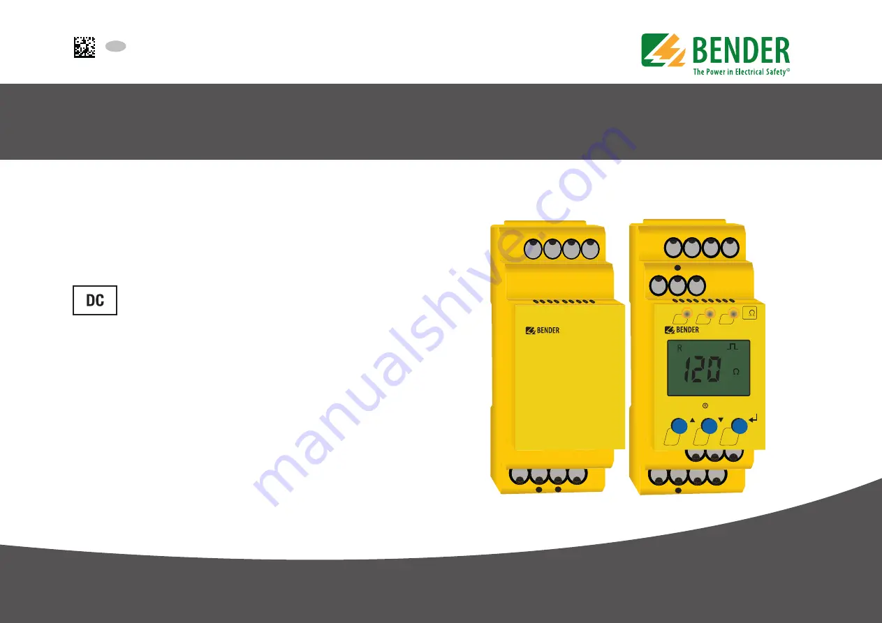
Insulation monitoring device for 
batteries up to DC 500 V
Software version: D0560

ON

T

R

MENU

AL1

AL2

k

<

k

ISOMETER

isoBAT425

L+

L-

E

KE

A1

A2

14

24

11

T/R

A

B

ZE420

E

E

E

L+

L-

E

ISOMETER® isoBAT425 with 
coupling impedance ZE420

i

soBAT425_D00308_04_M_XXEN/07.2020

Содержание ISOMETER isoBAT425

Страница 1: ...evice for batteries up to DC 500 V Software version D0560 ON T R MENU AL1 AL2 k k ISOMETER isoBAT425 L L E KE A1 A2 14 24 11 T R A B ZE420 E E E L L E ISOMETER isoBAT425 with coupling impedance ZE420 isoBAT425_D00308_04_M_XXEN 07 2020 ...

Страница 2: ...e Bender GmbH Co KG All rights reserved Reprinting only with permission of the publisher Subject to change Customer service Service hotline 0700 BenderHelp Telephone and Fax Carl Benz Strasse 8 35305 Gruenberg Germany Tel 49 6401 807 760 Fax 49 6401 807 629 E mail info bender service com READ THIS MANUAL AND ALL ACCOMPANYING DOCUMENTS CAREFULLY AND RETAIN FOR FUTURE REFERENCE ...

Страница 3: ... monitoring 9 3 2 5 Measuring pulse period duration and operating times 10 3 2 6 Fault diagnosis 10 3 2 6 1 Insulation fault to earth 10 3 2 6 2 Insulation fault between the battery strings cross fault 10 3 2 6 3 Battery voltage 11 3 2 7 Error codes 11 3 2 8 Connection monitoring 11 3 2 8 1 E KE monitoring 11 3 2 8 2 System connection monitoring 11 3 2 9 Reset and test 11 3 2 9 1 External test res...

Страница 4: ...bus register from the ISOMETER 23 7 1 1 Command of the master to the ISOMETER 23 7 1 2 The ISOMETER answers the master 23 7 2 Write Modbus register parameter setting 23 7 2 1 Command of the master to the ISOMETER 23 7 2 2 The ISOMETER answers the master 23 7 3 Exception code 24 7 3 1 Structure of the exception code 24 8 Modbus register assignment of the ISOMETER 25 8 1 Device specific data type of...

Страница 5: ...n making optimum use of the product This manual is intended for qualified personnel working in electrical engineering and electronics 1 2 Technical support Service and support For commissioning and troubleshooting Bender offers you 1 2 1 First level support Technical support by phone or e mail for all Bender products Questions regarding specific customer applications Commissioning Troubleshooting ...

Страница 6: ...ervice de Internet www bender de com 1 6 Warranty and liability Warranty and liability claims in the event of injury to persons or damage to property are excluded if they can be attributed to one or more of the following causes Improper use of the device Incorrect mounting commissioning operation and maintenance of the device Failure to observe the instructions in this operating manual regarding t...

Страница 7: ...r monitoring the insulation resistance RF as well as the voltage of a battery during its assembly from individual battery cells The ISOMETER mo nitors the insulation resistance RF of batteries with nominal system voltages of DC 0 400 V The maximum permissible system leakage capacitance Ce is 1 μF The resul ting measured values allow diagnosing the type and location of the insulation fault In order...

Страница 8: ...tring which are not interconnected During the second step the two strings are con nected to form a complete battery by means of another battery The resulting measured values allow diagnosing the type and location of the insulation fault In the LC display the faulty conductor is displayed with a plus or a minus sign preceding the value RF It is possible to assign the detected fault or the faulty co...

Страница 9: ...o gether The system leakage capacitance Ce is monitored on its compliance with the maximum permissible value for the ISOMETER If the measured value of the system leakage capacitance Ce exceeds 4 μF the device error E 07 with the alarm message Device er ror is issued The measurement method requires a low resistance connection between terminals L and L If the battery strings are still separated from...

Страница 10: ...tical and the nominal battery voltage Un is about 0 V it is very likely that the insulation fault is only located in one string The polarity of the residual voltages marks the affected string The affected battery cell can be calculated by means of the residual voltages UL e or UL e If there is an additional insulation fault in the other string determining the cell is almost impossible since severa...

Страница 11: ...t by setting the parameter S Ct off in the SEt menu This allows the ISOMETER to enter measurement mode quickly after connecting the supply voltage Us 3 2 8 Connection monitoring 3 2 8 1 E KE monitoring The E KE monitoring checks the connection between terminals E and KE and thereby ensures the connection to earth of the ISOMETER and the battery enclosure An error is reported with the code E 01 and...

Страница 12: ...ce command TESTI on BMS is the trigger the LCD indicates the texts tES and CAL A reset is only carried out after completing the test function Except triggering via the T R button the alarm relays retain the alarms active at the beginning of the text except the Device fault alarm during the test In addition the message test is issued on the alarm relays if it has been configured in the out menu and...

Страница 13: ...in the n c operating mode If S AL is activated during device start all alarms of the released threshold value comparisons are set and the measured resistance values are initialised with 0 Ω The alar ms of the individual threshold value comparisons remain set until the respective measu red value has reached the go status No hysteresis is taken into account and the alarms do not remain stored in the...

Страница 14: ... according to the config table are stored in the empty history memory Saving again is only possible after clearing the history memory via the menu During the start alarm phase and due to the message TEST no information is written to the history memory 3 2 17 Interface protocols The ISOMETER uses the serial hardware interface RS 485 with the following protocols BMS The BMS protocol is an essential ...

Страница 15: ...ystem DANGER Risk of fatal injury from electric shock Touching live parts of the system carries the risk of An electric shock Damage to the electrical installation Destruction of the device Before fitting the device and prior to working on the device connections make sure that the power supply has been disconnected Observe the rules for working on electrical installations If the ISOMETER is used i...

Страница 16: ...1 L KE A1 A2 Test Reset 14 24 11 K1 K2 T R L L1 PE N ON T R MENU AL1 AL2 k k ISOMETER isoBAT425 L L E KE A1 A2 14 24 11 T R A B COM465IP RS 485 A B R R on off E UL e UL e Bat 2 Rc RF1 Ce1 RF2 Ce2 Bat 1 Un L RF1 RF2 RF Ce Ce1 Ce2 Insulation fault to earth System leakage capacitance to earth Rc Insulation fault between the plus and minus strings cross fault 6 A 6 A J Y St Y 2x0 6 E E E E ZE420 E E E ...

Страница 17: ...e ISOMETER The device carries out a calibration a self test and adjusts itself to the IT system to be monitored When high system leakage capacitances are involved this procedure may take up to 30 s The standard display then appears showing the present insula tion resistance RF e g The pulse symbol signals an error free update of the resistance measured value If the measuring value cannot be update...

Страница 18: ...t display Function ON AL1 AL2 green on yellow alarm yellow alarm T Test button press 1 5 s By pressing and holding the test button the display elements are indicated Up button R Down button Reset button press 1 5 s MENU ENTER MENU button press 1 5 s 1 U Nominal system voltage Un R Insulation resistance RF C System leakage capacitance Ce 2 Monitored conductor e g Display indication Measured paramet...

Страница 19: ...meter selection 5 3 AL menu 5 3 1 Response value setting The two parameters that monitor the insulation resistance RF R1 and R2 can be found in the response value menu AL The value R1 can only be set higher than the value R2 If the insulation resistance RF reaches or falls below the activated values R1 or R2 this leads to an alarm message If RF exceeds the values R1 or R2 plus the hysteresis see t...

Страница 20: ... L r1 R2 Ω off r2 R2 Ω on Alarm R2 Fault RF at L r1 U V off r2 U V off Alarm Un undervoltage r1 U V off r2 U V on Alarm Un Overvoltage r1 U V on r2 U V off Message battery voltage Un is ok r1 test off r2 test off Manually started device test 1 2 1Err 2 Err FAC Factory setting Cs Customer settings LED off LED flashes LED on 5 4 3 Fault memory configuration FAC Factory setting Cs Customer settings 5...

Страница 21: ...he standard display after a maximum of 5 minutes The pulse symbol indicates a current measured value If this symbol does not appear the measurement is still running and the latest valid measured value will be displayed The symbols or will be displayed additionally to the measured value when a response value has been reached or violated or the measured value is below or exceeds the measuring range ...

Страница 22: ...suring device interface BMS bus protocol ASCII characters are used for the data transfer BMS channel no Operation value Alarm 1 RF Pre alarm R1 2 RF Alarm R2 3 Ce 4 Un Undervoltage 5 Un Overvoltage 6 Connection fault earth E 01 7 Connection fault system E 02 8 All other device faults E xx 9 Fault location 10 UL e Un battery voltage ok 11 UL e 12 Update counter 13 14 15 ...

Страница 23: ...ss 0x03 Byte 1 Function code 0x03 Byte 2 3 Start address 0x03EB Byte 4 5 Number of registers 0x0001 Byte 6 7 CRC16 Checksum 0xF598 Byte Name Example Byte 0 ISOMETER Modbus address 0x03 Byte 1 Function code 0x03 Byte 2 Number of data bytes 0x02 Byte 3 4 Data 0x0047 Byte 7 8 CRC16 Checksum 0x81B6 7 2 Write Modbus register parameter setting Registers in the device can be modified with the Modbus comm...

Страница 24: ...ults can be narrowed down 7 3 1 Structure of the exception code Exception code Description 0x01 Impermissible function 0x02 Impermissible data access 0x03 Impermissible data value 0x04 Internal fault 0x05 Acknowledgement of receipt answer will be time delayed 0x06 Request not accepted repeat request if necessary Byte Name Example Byte 0 ISOMETER Modbus address 0x03 Byte 1 Function code 0x03 0x80 0...

Страница 25: ...m 1024 to 1027 Fault location in 1022 no alarm 1028 to 1031 1032 to 1035 Measured value update counter 1022 no alarm Device error 115 Device error Register Property Description Format Unit Value range 3000 RW Reserved 3001 RW Pre alarm value resis tance measurement R1 UINT 16 kΩ R2 5000 3002 RW Reserved 3003 RW Alarm value resis tance measurement R2 UINT 16 kΩ 10 R1 3004 RW Reserved 3005 RW UBattH...

Страница 26: ...UINT 16 Bit 10 Bit 1 3028 RW Alarm assignment of alarm relay 2 r2 UINT 16 Bit 10 Bit 1 3029 RW Measuring pulse period duration UINT 16 0 auto 0 8 s 1 auto 2 0 s 2 0 8 s 3 2 0 s 4 4 0 s 5 8 0 s 8003 WO Factory settings for all parameters UINT 16 0x6661 fa 8004 WO Factory setting only for parameters resetta ble by FAC UINT 16 0x4653 FS 8005 WO Start device test UINT 16 0x5445 TE Register Property De...

Страница 27: ...te LoByte HiByte LoByte HiByte LoByte HiByte LoByte Floating point value Float Alarmtypeand test type AT T Range and unit R U Channel description Word 0x00 0x01 Byte HiByte LoByte HiByte LoByte Bit 31 30 24 23 22 16 15 8 7 0 S E E E E E E E E M M M M M M M M M M M M M M M M M M M M M M M 8 1 2 2 AT T Alarm type and test type internal external The alarm type is coded by the bits 0 to 2 Bits 3 4 and...

Страница 28: ...signed to each alarm relay For the assignment of each alarm re lay a 16 bit register is used with the bits described below The following table applies to alarm relay 1 and alarm relay 2 in which x stands for the alarm relay number A set bit activates the specified function A set bit activates the specified function Bit Display indication Meaning 0 Reserved When reading always 0 When writing any va...

Страница 29: ...erequired Text representationis not necessary in this case Value Description of parameters 1023 0x3FF Parameter measured value invalid The menu item of this parameter is not displayed 1022 0x3FE No measured value no message 1021 0x3FD Measured value parameter inactive 1020 0x3FC Measured value parameter only temporarily inactive e g while transmitting a new parameter Indication in the menu 1019 0x...

Страница 30: ...oltage Un VDC 1234 5 Residual voltage UL e VDC 1234 5 Residual voltage UL e VDC 123 Insulation fault location 100 100 1234 Alarm message hexadecimal without leading 0x The alarms are included in this value with the OR function Assignment of the alarms 0x0002 Device fault 0x0004 Prewarning insulation resistance RF at L 0x0008 Prewarning insulation resistance RF at L 0x000C Prewarning insulation res...

Страница 31: ... circuit Measuring voltage Um 12 V Measuring current Im at RF ZF 0 Ω 110 μA Internal resistance Ri Zi 115 kΩ Permissible system leakage capacitanceCe 1 μF Response values Response value Ran1 11 5000 kΩ 1500 kΩ Response value Ran2 10 4900 kΩ 1000 kΩ Relative uncertainty Ran 15 at least 2 kΩ Hysteresis Ran 25 at least 1 kΩ Voltage detection UBattH 4 500 V 400 V Voltage detection UBattL 3 499 V 378 V...

Страница 32: ...21 3 1 1K22 except condensation and formation of ice Classification of mechanical conditions acc to IEC 60721 Stationary use IEC 60721 3 3 3M11 Transport IEC 60721 3 2 2M4 Long term storage IEC 60721 3 1 1M12 Connection Connectiontype push wire terminal Nominal current 10A Cross section AWG 24 14 Stripping length 10 mm Rigid 0 2 2 5 mm2 Flexible without ferrules 0 75 2 5 mm2 Flexible with ferrules...

Страница 33: ... mm2 Opening force 50 N Test opening diameter 2 1 mm Other Operating mode continuous operation Mounting cooling slots must be ventilated vertically Degree of protection built in components DIN EN 60529 IP30 Degree of protection terminals DIN EN 60529 IP20 Enclosure material polycarbonate DIN rail mounting acc to IEC 60715 Screw fixing 2 x M4 with mounting clip Weight 150 g 10 2 Standards approvals...

Страница 34: ...tallation and connection 15 Intended use 7 Interface protocols 14 BMS 14 IsoData 14 Modbus RTU 14 IsoData Data string 30 M Measuring times 13 Menu AL 19 out 20 SEt 21 t 21 Overview 19 Modbus Register assignment 25 Monitoring for undervoltage and overvoltage 9 insulation resistance R mode 9 O Operating time 13 Operation 18 Ordering details 33 P Password protection 14 R Response delay time 13 Respon...

Страница 35: ...8 35305 Grünberg Germany Tel 49 6401 807 760 Fax 49 6401 807 629 E Mail info bender service com Web http www bender de BENDER Group Bender GmbH Co KG Postbox 1161 35301 Grünberg Germany Londorfer Straße 65 35305 Grünberg Germany Tel 49 6401 807 0 Fax 49 6401 807 259 E Mail info bender de Web www bender de ...

Отзывы: