
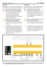


Connection
1. Connect terminals E and KE to earth (PE).
2. Connect A and B to the BMS bus.
3. Connect terminal S to the shield of the bus
line (only at the end of the line).
4. Connect terminal L1/+ to L1/+ of the IT sys-
tem (with one 1 A fuse each).
5. Connect terminal L2/– to L2/– of the IT sys-
tem (with one 1 A fuse each).
6. Connect terminal A1/A2 to the supply volta-
ge Us (with one 2 A fuse each).
7. Connect the alarm outputs 11/12/14,
21/22/24 and 31/32/34.
Legend
Terminal
Connections
I1–, I1+
I2–, I2+
Configurable digital inputs
(e.g. Test, Reset)
CAN1, CAN2
No function
RS-485 Term.
DIP switch for the termination of the
RS-485 interface
A, B, S
Serial RS-485 interface
k, l, kT, lT
No function
31, 32, 34
Relay output for internal device errors
and connection faults
21, 22, 24
Relay output for alarm insulation fault
11, 12, 14
Relay output for alarm insulation fault
E, KE
Separate connections of E (earth)
and KE (control earth) to PE
A1, A2
Connection to
U
s = DC 24 V
L1/+
Coupling terminal L1/+
L2/–
Coupling terminal L2/–
SS8103
No function
ST6101
Alarm resetting
µSDCard
No function
Anschluss
1. Klemme E und KE an Erde (PE) anschließen.
2. Klemme A und B an BMS-Bus anschließen.
3. Klemme S an den Schirm der Bus-Leitung an-
schließen (nur an einem Ende der Leitung).
4. Klemme L1/+ an L1/+ des IT-Netzes anschlie-
ßen (mit je 1 A-Sicherung).
5. Klemme L2/– an L2/– des IT-Netzes anschlie-
ßen (mit je 1 A-Sicherung).
6. Klemme A1/A2 an die Versorgungsspannung
Us anschließen (mit je 2 A-Sicherung).
7. Meldeausgänge 11/12/14, 21/22/24 und
31/32/34 anschließen.
Legende
Klemme
Anschlüsse
I1–, I1+
I2–, I2+
Konfigurierbare digitale Eingänge
(z. B. Test, Reset)
CAN1, CAN2
Ohne Funktion
RS-485 Term.
DIP-Schalter zur Terminierung der
RS-485-Schnittstelle
A, B, S
Serielle Schnittstelle RS-485
k, l, kT, lT
Ohne Funktion
31, 32, 34
Relaisausgang für interne Gerätefehler
und Anschlussfehler
21, 22, 24
Relaisausgang für Alarm Isolationsfehler
11, 12, 14
Relaisausgang für Alarm Isolationsfehler
E, KE
Separate Anschlüsse von E (Erde)
und KE (Kontrollerde) an PE
A1, A2
Versorgungsspannung
U
s DC 24 V
L1/+
Ankopplung Klemme L1/+
L2/–
Ankopplung Klemme L2/–
SS8103
Ohne Funktion
ST6101
Rücksetzen von Alarmen
µSDCard
Ohne Funktion
ISOMETER® isoxx1685Dx-x25
isoxx1685Dx-x25_D00272_02_Q_DEEN / 04.2019 5


