background image

iso165C_D00154_03_M_XXEN/01.2019

7

Safety information

2.  Safety information

2.1 General safety instructions

Part of the device documentation in addition to this manual is the enclosed "Safety in-
structions for Bender products".  

If the device is used outside the Federal Republic of Germany, the applicable local stand-
ards and regulations must be complied with. The European standard EN 50110 can be 
used as a guide.

2.2 Intended use

The ISOMETER® iso165C and ISOMETER® iso165C-1 monitor the high-voltage (HV) insula-
tion resistance between the car chassis and the active HV components of an unearthed 
DC drive system (IT system) in electric vehicles with supply voltages of DC 0 V...600 V. The 
insulation condition is monitored on the DC side as well as on the AC motor side of the 
electrical drive system. Existing insulation faults will be reliably signaled even under high 
system interferences, which can be caused by motor control processes, acceleration or 
energy recovery for example.

Both ISOMETER®s feature a CAN bus interface and can be easily integrated into an exist-
ing CAN environment in hybrid or fully electric vehicles.

DANGER

Risk of electrocution due to electric shock!

Touching live parts of the system carries the risk of: 

    • An electric shock 

    • Damage to the electrical installation 

    • Destruction of the device 

Before installing and connecting the device, make sure that the installa-
tion has been de-energised. Observe the rules for working on electrical in-
stallations.

Only skilled persons are permitted to carry out the work necessary to install,
commission and run a device or system.

Ensure the correct rated input voltage and supply voltage is applied. For insulation or 
voltage tests, the ISOMETER® must be separated from the IT system for the duration of the 
test. To check that the device has been properly connected, perform a functional test be-
fore commissioning the system. It is necessary to examine whether the initial settings 
meet the requirements of the IT system. 

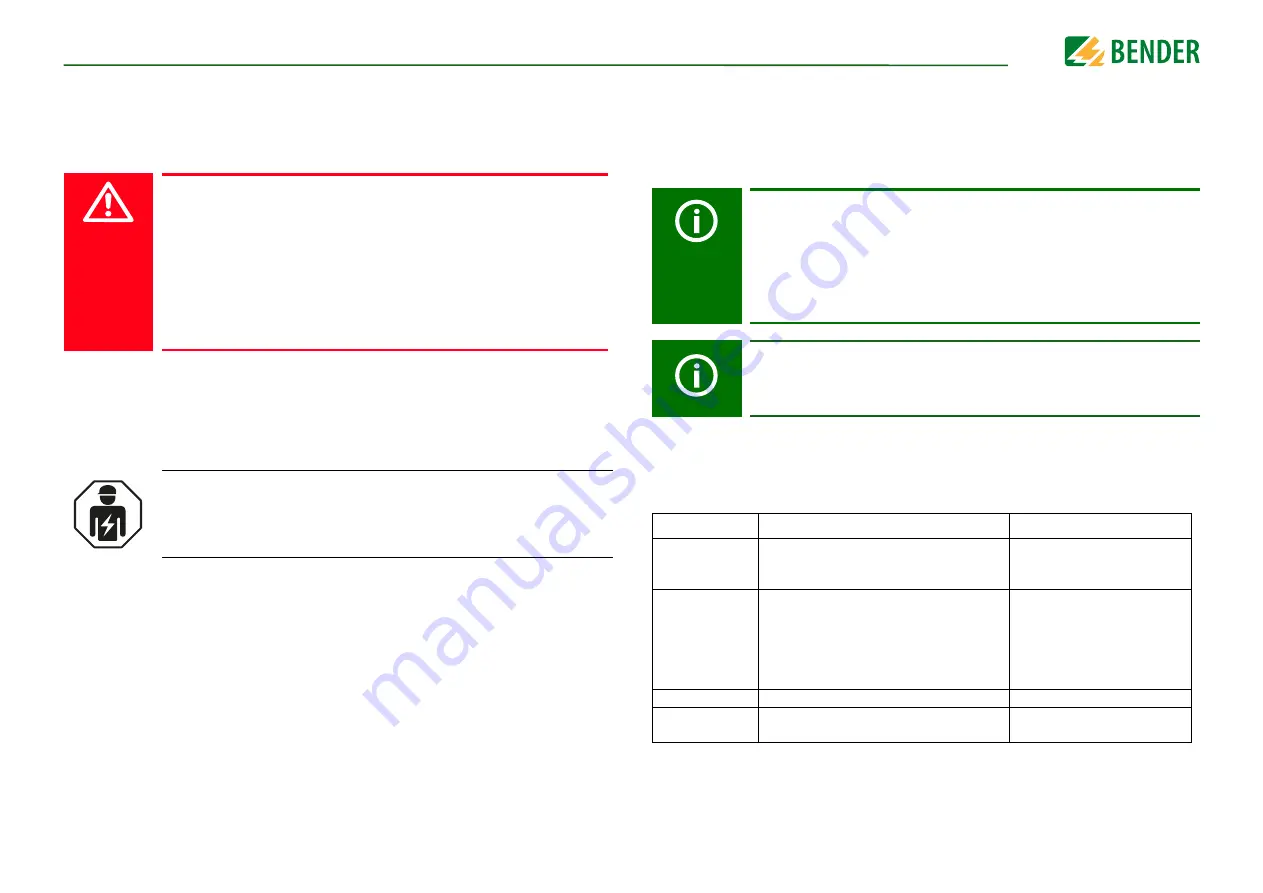
 2.2.1  ISOMETER® iso165C and ISOMETER® iso165C-1 comparison

While the ISOMETER® iso165C and ISOMETER® iso165C-1 are similiar in many aspects (re-
fer to the features list on 

page 8

 the main differences between the two are shown in the 

table below:

With reference to the general application of an IMD in IT systems, only one
active IMD in a galvanically interconnected system is permitted. If IT sys-
tems are to be interconnected via a coupling switch, it must be ensured via
a supervisory unit that all other IMDs are separated from the IT system and
switched to inactive. IT systems coupled via capacitors or diodes can also
influence the insulation monitoring system. For this reason, central control
of the various IMDs must be implemented.

In the event of an ISOMETER® alarm message, the insulation fault should
be eliminated as quickly as possible.

Feature

iso165C

iso165C-1

Contains an out-
put driver

No 

Yes. Error and Warning signals 
are available on the separated 
high-side driver 

Coupling relays at 
power on

The HV coupling relays of the HV1 voltage 
path are, by default, open and therefore no 
valid voltage and insulation resistance mea-
surements are possible until these relays are 
closed, which must be carried out using an 
external command

The HV coupling relays of the 
HV1 voltage path are automati-
cally closed at power on

Baud rate

250 kBaud

500 kBaud

Terminating resis-
tance

124 Ω


internally

None

Содержание B91068175

Страница 1: ...EN Manual iso165C_D00154_03_M_XXEN 01 2019 ISOMETER iso165C iso165C 1 Insulation Monitoring Device IMD for unearthed DC drive systems IT systems in electric vehicles...

Страница 2: ...Bender GmbH Co KG All rights reserved Reprinting only with permission of the publisher Subject to change Customer service Service hotline 0700 BenderHelp Telephone and Fax Carl Benz Stra e 8 35305 Gr...

Страница 3: ...agram 100 2 2 k resistance at HST_1 HST_2 13 5 3 Typical application 14 5 3 1 Special application notes 14 6 Operation 15 6 1 Messages 15 6 2 IMD_Info 15 6 3 IMD_Request 15 6 3 1 Example 16 6 4 IMD_Re...

Страница 4: ...MC_R_ISO_CNT 22 7 3 10 D_IMC_MANUFACT_INDEX 22 7 3 11 D_IMC_MANUFACT_DATA 22 7 3 12 D_IMC_HV_1 22 7 3 13 D_IMC_HV_2 22 7 3 14 D_IMC_VERSION_INDEX 22 7 3 15 D_IMC_VERSION 23 7 3 16 D_IMC_TEST_CNT 23 7...

Страница 5: ...ring and electronics 1 2 Technical support Service and support For commissioning and troubleshooting Bender offers you 1 2 1 First level support Technical support by phone or e mail for all Bender pro...

Страница 6: ...age to property are excluded if they can be attributed to one or more of the following causes Improper use of the device Incorrect mounting commissioning operation and maintenance of the device Failur...

Страница 7: ...re the correct rated input voltage and supply voltage is applied For insulation or voltage tests the ISOMETER mustbe separated from the IT system forthe durationofthe test To check that the device has...

Страница 8: ...nal galvanic separa tion connector 1 is connected to low voltage LV areas and connectors 2 and 3 are con nected to the HV areas in the car environment Due to its space saving design and optimized meas...

Страница 9: ...ing voltages HV1 HV2 and the insulation resist ance In the ISOMETER iso165C 1 however the HV coupling relays of the HV1 voltage path are automatically closed at power on The initial measurement values...

Страница 10: ...iso165C_D00154_03_M_XXEN 01 2019 10 4 Dimensions 4 1 Device dimensions 111 4 2 96 0 6 92 01 97 85 141 82 2 43 2 1 82 0 6 6 4x A A DMC 4 0 5 4x Max permissible unevenness between the mounting points...

Страница 11: ...nent Properties 1 Housing PBT GF30 black UL Standard UL94 V0 2 Connector pin Cu alloy tin plated 3 Label White Polyester foil 4 Bracket PBT GF30 black UL Standard UL94 V0 Section view A A Scale 2 1 11...

Страница 12: ...ION Risk of injury from sharp edged terminals Handle housing and terminals with care CAUTION In every conductively connected system only one IMD may be connected When performing insulation and dielect...

Страница 13: ...ver 1 iso Warning iso165C 1 only 5 HS CAN_L 6 HS CAN_H 7 T_31_E_2 vehicle internal earthing structure 8 T_30 12V switched supply 5A fuse Ignition and Charging FET Connector 2 HV1 for Insulation monito...

Страница 14: ...g a 10 offset to the real insulation value The HV2 terminals could be used for voltage monitoring at disconnected HV sections e g voltage monitoring of a charging plug RF3 RF2 RISO AC G RCon1 RF1 Ri R...

Страница 15: ...ill always generate an answer message IMD_Response It can handle Control CTL SET and GET commands A request has the following format Definitions of DataWord1 and DataWord2 for different commands can b...

Страница 16: ...ET_VERSION 0x5A S_IMC_GET_TEST_CNT 0x3D S_IMC_GET_MANUFACTURER CAN ID Request DLC CMD Data1 Data2 Data3 Data4 0x22 0x5 0xCA 0x00 0x00 0x00 0x00 6 4 IMD_Response IMD_Response is generated exclusively a...

Страница 17: ...rol response data value IS_ IMD Set response data value IG_ IMD Get response data value II_ IMD Info data value 7 2 Command descriptions The message parameters are coded in bytes 2 to 5 and provide th...

Страница 18: ...sponse CMD 0x29 0x29 DataWord1 D_IMC_R_ISO_WRN_THR D_IMC_R_ISO_WRN_THR DataWord2 0 0 IMD_Request IMD_Response CMD 0x2B 0x2B DataWord1 D_IMC_MEAN_FACTOR D_IMC_MEAN_FACTOR DataWord2 0 0 7 2 2 4 S_VIFC_S...

Страница 19: ...esponse CMD 0x3C 0x3C DataWord1 0 D_IMC_MEAN_FACTOR DataWord2 0 0 IMD_Request IMD_Response CMD 0x36 0x36 DataWord1 0 D_IMC_HV_1 DataWord2 0 0 7 2 3 8 S_IMC_GET_HV_2 This command requests the HV value...

Страница 20: ...S DataWord2 0 D_VIFC_HV_RELAIS_STATE IMD_Request IMD_Response CMD 0xE2 0xE2 DataWord1 0 D_VIFC_IMC_ALIVE DataWord2 0 0 IMD_Request IMD_Response CMD 0xDE 0xDE DataWord1 D_IMC_VERSION_INDEX D_VIFC_VERSI...

Страница 21: ...running 0 NotRunning 1 Running 4 Self test running 0 NotRunning 1 Running 5 Insulation warning 0 NoWarning 1 Warning 6 Reserved 7 Reserved 8 Reserved 9 Reserved 10 Reserved 11 Reserved 7 3 6 D_IMC_STA...

Страница 22: ...aracter from the manufacturer s string Unit k Default 0 Resolution 1 Range 0 50 000 Value Description 0 Unknown 1 Fault on HV1_NEG 2 Fault on HV1_POS Unit Counter value Default 0 Resolution 1 Range 0...

Страница 23: ...Default 0 Resolution 1 Range 0 65 535 Value Description 0 HV_1_NEG relay 1 HV_1_POS relay 100 Unknown Value Description 0 Disabled 1 Enabled 100 Unknown 7 3 19 D_VIFC_LOCK_MODE This data value represe...

Страница 24: ...ault 2 Performance error The VIFC has received the analogue Alive signal but was not able to evaluate it correctly 100 Unknown The VIFC is not receiving the analogue Alive signal from the IMC 7 3 25 D...

Страница 25: ...37 Repeated or missing frame VIFC error codes Value Description 1000 Command locked 1001 Queue full Command rejected 1002 Command unavailable Measurement Off 1032 Timeout 10 ms incomplete frame 1033 C...

Страница 26: ...down resistor tochassis ground KL 31 is required Not protected against a short circuit inthe event that KL 31 is missing Therefore a 100 resistor is required on each driver output Response Values iso...

Страница 27: ...customer setting XXX k Alarm1 Warning 40 k 2 M customer setting XXX k DC 0 600 V DC 12 V B91068176C Type Art No iso165C connecting kit B91068503 8 3 Standards corresponding norms and regulations 8 3 1...

Страница 28: ...pinning arrangement 13 Control Control CTL 15 D Data value descriptions 20 Device CAN interface 9 component housing and mounting 11 description 8 features 8 functional description 8 HS CAN bus 8 IMC...

Страница 29: ...so165C_D00154_03_M_XXEN 01 2019 29 S Safety 7 work activities 7 Standards EMC 27 environmental 27 general 27 T Technical data 26 connectors 26 other 27 U UART 8 W Wiring diagram 100 2 2 k resistance 1...

Страница 30: ......

Страница 31: ......

Страница 32: ...35305 Gr nberg Germany Tel 49 6401 807 760 Fax 49 6401 807 629 E Mail info bender service com Web http www bender de BENDER Group Bender GmbH Co KG Postbox 1161 35301 Gr nberg Germany Londorfer Stra...

Отзывы: