background image

Manual

EN

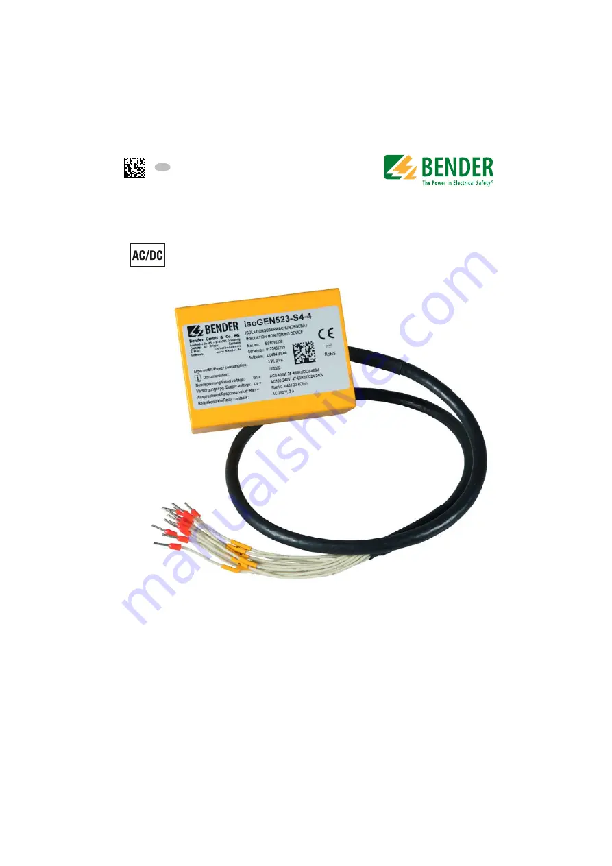
ISOMETER® isoGEN523-S4-4

Insulation monitoring device for 
unearthed AC, AC/DC and DC systems (IT systems) 
up to 3(N)AC, AC 400 V, DC 400 V 
Suitable for use in applications using generators 
according to DIN VDE 0100-551 
Software version: D0494 V1.xx 

isoGEN523_D00320_04_M_XXEN/06.2018

Содержание B91016330

Страница 1: ...n monitoring device for unearthed AC AC DC and DC systems IT systems up to 3 N AC AC 400 V DC 400 V Suitable for use in applications using generators according to DIN VDE 0100 551 Software version D04...

Страница 2: ...ermany Londorfer Str 65 35305 Gruenberg Germany Tel 49 6401 807 0 Fax 49 6401 807 259 E mail info bender de www bender de Bender GmbH Co KG All rights reserved Reprinting only with permission of the p...

Страница 3: ...7 Disposal 9 2 Safety instructions 10 2 1 General safety instructions 10 2 2 Work activities on electrical installations 10 2 3 Intended use 11 3 Device description 12 3 1 Device features 12 3 2 Func...

Страница 4: ...5 2 1 Relay signalling assignment r1 and r2 24 5 2 2 Fault memory configuration 24 5 3 Interface configuration 25 5 4 Time configuration 25 5 5 Function configuration 26 5 6 Measured value description...

Страница 5: ...8 1 2 Measured values 34 8 1 2 1 Float Floating point value of the channels 35 8 1 2 2 AT T Alarm type and test type internal external 35 8 1 2 3 R U Range and unit 36 8 1 3 Alarm assignment of the re...

Страница 6: ...ual is intended for qualified personnel working in electrical engineering and electronics DANGER This signal word indicates that there is a high risk of danger that will result in death or serious inj...

Страница 7: ...2 Repair service Repair calibration update and replacement service for Bender products Repairing calibrating testing and analysing Bender products Hardware and software update for Bender devices Deliv...

Страница 8: ...For software products the Softwareklausel zur berlassung von Standard Software als Teil von Lieferungen Erg nzung und nderung der Allgemeinen Lieferbedingungen f r Erzeugnisse und Leistungen der Elekt...

Страница 9: ...e device Furthermore the rules and regulations that apply for ac cident prevention at the place of use must be observed 1 7 Disposal Abide by the national regulations and laws governing the disposal o...

Страница 10: ...uropean standard EN 50110 can be used as a guide Onlyqualifiedpersonnelarepermittedtocarryouttheworknecessaryto install commission and run a device or system DANGER Risk of fatal injury due to electri...

Страница 11: ...set tings must be made on the equipment in order to adapt it to local equipment and op erating conditions Please heed the limits of the range of application indicated in the technical data Any use ot...

Страница 12: ...y can be activated RS 485 galvanically isolated including the following protocols BMS interface Bender measuring device interface for data exchange with other Bender components Modbus RTU IsoData for...

Страница 13: ...00 or L2 100 Calculating the fault distribution is not possible in this case If the values RF or Un reach or violate the activated response values for the period ton without interruption an alarm is s...

Страница 14: ...n deacti vated The alarm will be deleted when the limit values plus hysteresis are no longer violated 3 2 7 Self test Device fault The integrated self test function checks the function of the insulati...

Страница 15: ...voltages UL1e and UL2e as well as the faulty conductor R and is dependant on the insulation resistance RF and the system leakage capacitance Ce of the system to be monitored System disturbances may l...

Страница 16: ...FAC Activating the factory settings will reset all modified settings with the exception of the interface parameters to the default upon delivery 3 2 12 External combined test or reset button T R Reset...

Страница 17: ...r via bus systems and networks Modbus RTU messages have a 16 bit CRC Cyclic Redundant Checksum which guarantees reliability IsoData The ISOMETER continuously sends an ASCII data string with a cycle of...

Страница 18: ...via the RS 485 interface The IsoData protocol is activated by setting Adr 0 The parameter value for the baud rate indicates the activated BMS protocol In this case the baud rate for the BMS protocol...

Страница 19: ...e to electric shock Touching live parts of the system carries the risk of An electric shock Damage to the electrical installation Destruction of the device Before installing and connecting the device...

Страница 20: ...of a protective device a 6 A fuse is recommended Devices for protec tion against short circuit in conformity with IEC 60364 4 43 for the connection of termi nals L1 L2 to the IT system to be monitore...

Страница 21: ...valid if the cable is installed permanently US 4 L2 5 KE 1 A1 2 A2 Test Reset 10 14 11 24 9 11 K1 K2 6 T R 3 L1 L1 L2 PE L3 7 A 8 B 12 E COM465IP RS 485 Signal cable Wires 1 12 isoGEN523 S4 4 1 2 3 4...

Страница 22: ...nsulation fault The ISOMETER in the system being monitored has to be tested with a suita ble resistance to earth Wire number Terminal Connections 1 2 A1 A2 Connection to the supply voltage Us via fuse...

Страница 23: ...ltage can be activat ed or deactivated The maximum undervoltage value is limited by the overvoltage val ue FAC Factory settings Cs Customer settings 5 2 Configuration of the relay operating mode FAC F...

Страница 24: ...mer settings 5 2 2 Fault memory configuration FAC Factory settings Cs Customer settings K1 r1 K2 r2 Alarm description Available via FAC Cs FAC Cs Modbus off on Device error E xx X on off Pre alarm R1...

Страница 25: ...us and activates isoData with continu ous data output 115k2 8E1 X X 1 2k 115k Baud rate BMS bus 9k6 7E1 1 2k 115k2 Modbus variable variable X X 8E1 8o1 8n1 8E1 Modbus 8E1 8 data bits even parity 1 sto...

Страница 26: ...h connected DC DC dc DC system X X nEt on Test of the system connection during device test X X S Ct on Device test during device start X X FAC Restore factory settings X X SYS For Bender Service only...

Страница 27: ...inter face BMS bus protocol Data transmission generally makes use of ASCII characters BMS channel no Operation value Alarm 1 RF Pre alarm R1 2 RF Alarm R2 3 4 Un Undervoltage 5 Un Overvoltage 6 Conne...

Страница 28: ...the master to the ISOMETER In the following example the master of the ISOMETER requests the content of the register 1003 with the address 3 The register contains the channel description of measuring c...

Страница 29: ...down Byte Name Example Byte 0 ISOMETER Modbus address 0x03 Byte 1 Function code 0x10 Byte 2 3 Start register 0x0BBB Byte 4 5 Number of registers 0x0001 Byte 6 Number of data bytes 0x02 Byte 7 8 Data...

Страница 30: ...otocol 30 isoGEN523_D00320_04_M_XXEN 06 2018 7 3 1 Structure of the exception code Byte Name Example Byte 0 ISOMETER Modbus address 0x03 Byte 1 Function code 0x03 0x80 0x83 Byte 2 Data exception code...

Страница 31: ...Device error Without alarm Alarm 1 Alarm 2 1000 to 1003 RF Insulation fault 71 no alarm RF Insulation fault 1 prewarning RF Insulation fault 1 alarm Connection earth 102 device error 1004 to 1007 100...

Страница 32: ...tivation alarm value undervoltage U UINT 16 0 Inactive 1 Active 3009 RW Alarm value under voltage U UINT 16 V 10 U 3010 RW Activation alarm value overvoltage U UINT 16 0 Inactive 1 Active 3011 RW Alar...

Страница 33: ...Hd 3024 RW Test of the system con nection during device test nEt UINT 16 0 Inactive 1 Active 3025 RW Device test during device start S Ct UINT 16 0 Inactive 1 Active 3026 RW Request stop mode 0 deacti...

Страница 34: ...channel is shown with the example of channel 1 9800 to 9809 RO Device name UNIT 16 ASCII refer to Chapter 8 1 1 9820 RO Software ID number UINT 16 Software D number 9821 RO Software version number UI...

Страница 35: ...te LoByte HiByte LoByte Bit 31 30 24 23 22 16 15 8 7 0 S E E E E E E E E M M M M M M M M M M M M M M M M M M M M M M M Bit 7 6 5 4 3 2 1 0 Meaning Test external Test internal Reserved Reserved Reserve...

Страница 36: ...bits 0 to 4 are coded Bits 6 and 7 describe the validity range of a value Bit 5 is reserved The complete byte is calculated from the sum of the unit and the range of validity Bit 7 6 5 4 3 2 1 0 Meani...

Страница 37: ...any value 1 x Err Device error E xx 2 rx R1 Pre alarm R1 fault RF at L1 3 rx R1 Pre alarm R1 fault RF at L2 4 rx R2 Alarm R2 fault RF at L1 5 rx R2 Alarm R2 fault RF at L2 6 rx U V Alarm message Un u...

Страница 38: ...ments 0 1 0x01 Insulation fault 71 0x47 Insulation fault Insulation resistance RF in 76 0x4C Voltage Measured value in V 77 0x4D Undervoltage 78 0x4E Overvoltage 82 0x52 Capacitance Measured value in...

Страница 39: ...value parameter inactive 1020 0x3FC Measured value parameter only temporarily inactive e g while trans mitting a new parameter 1019 0x3FB Parameter measured value value unit not displayed 1018 0x3FA P...

Страница 40: ...tage Un VtrueRMS Nominal system voltage type AC or unknown DC 1234 Residual voltage UL1e VDC 1234 Residual voltage UL2e VDC 123 Insulation fault location 100 100 123456 Reserved 1234 Alarm message hex...

Страница 41: ...y III Rated impulse voltage IC1 IC2 4 6 kV IC2 IC3 4 4 kV IC3 IC4 4 kV Rated insulation voltage IC1 IC2 4 400 V IC2 IC3 4 250 V IC3 IC4 250 V Pollution degree 3 Safe isolation reinforced insulation be...

Страница 42: ...Relative uncertainty U 5 at least 5 V Relative uncertainty depending on the frequency 400 Hz 0 015 Hz Hysteresis U 5 at least 5 V Time response Response time tan at RF 0 5 x Ran and Ce 1 F acc to IEC...

Страница 43: ...2A 0 1 A Minimum contact rating 1 mA at AC DC 10 V Environment EMC EMC IEC 61326 2 4 Ambient temperatures Operation 40 70 C Transport 40 85 C Storage 40 70 C Classification of climatic conditions acc...

Страница 44: ...h the following standards DIN EN 61557 8 VDE 0413 8 2015 12 Ber1 2016 12 IEC 61557 8 2014 COR1 2016 DIN VDE 0100 551 2017 02 Subject to change The specified standards take into account the edition val...

Страница 45: ...Technical data 45 isoGEN523_D00320_04_M_XXEN 06 2018...

Страница 46: ...6 I Important information 6 Inspection transport and storage 8 Installation 19 screw fixing 20 Intended use 11 Interface protocols BMS 17 IsoData 17 Modbus RTU 17 IsoData data string 40 Isolation fro...

Страница 47: ...Safety instructions 10 Self test Automatic 14 Self test Device fault 14 Service 7 Signalling assignment 15 Standards and certifications 44 Support 7 T Technical data 41 Technical support 7 Training co...

Страница 48: ...ermany Londorfer Str 65 35305 Gruenberg Germany Tel 49 6401 807 0 Fax 49 6401 807 259 E mail info bender de www bender de Bender GmbH Co KG All rights reserved Reprinting only with permission of the p...

Отзывы: