


16
ATICS-DIO_D00080_03_Q_DEEN / 11.2020
ATICS-...-DIO
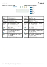
Menu
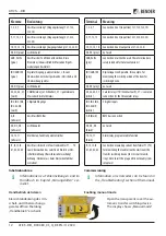
Press the „MENU“ button to open the main menu.
• Press or to go up resp. down one menu level.
• Press to confirm the selected menu item.
• Press „ESC“ to leave the menu.
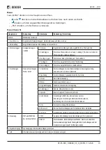
Menu overview
Main menu
Meaning
Submenu
Meaning/ Setting
Exit
Exit menu mode
1. Alarm/ meas. val.
Displays current status messages, alarm messages and measured values
2. Changeover
Displays information on the changeover function (number, test)
3. History/Logger
Displays logger
information
1. History
Alarm messages and tests which have been performed: value and time
2. Data logger
History of measured values: Line 1, Line 2, position, load current in the TN
system I(3), insulation, transformer load
3. Config. Logger
History of the „Settings“ menu: value and time
4. Test logger
History of the tests of the changeover switch carried out
5. Service logger
History of the service activities carried out
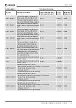
4. Settings
Various settings for
the device
1. Changeover
Setting the date and time, system, switching back interlocking function,
preferred supply, generator, test and service interval
2. Voltage
Delay times, voltage ranges, hysteresis
3. Current
Short-circuit detection
4. Relay
Mode of operation and relay mode
5. Digital input
Mode of operation, function, delay
6. Data logger
Modify, overwrite, delete
7. Language
Deutsch, English, Francais, Polski
8. Interface
Setting the BMS bus address of this device. Allow the settings to be
changed via the interface. Allow a test to be run via interface.
9. Clock
Set date format and date and time
10. Password
Enable resp. set password for settings and test
11. Service
Only for settings to be made by authorised Bender Service personnel
5. Control
Run TEST and RESET
for the device
1. TEST
Isometer, changeover, last changeover saved as a test, generator
2.RESET
Reset alarm messages, cancel the switching back interlocking function,
change the alarm value for the max. permissible number of changeover
operations performed and the max. permissible number of operating
hours
6. Digital input
Display voltage level of the digital input
7. Info
Display information on device type and firmware versions


