A D 2 4 0 2 - 9 6 - O P E R A T I N G M A N U A L
Appendix
2
Jitter and it’s Effects
Much Confusion Exists over Jitter: How and Where to Measure It, and How to
Eliminate It
The phase modulation effects of sample clock jitter in any A-to-D converter become a
permanent part of your recording. For that reason, great effort has been invested eliminating
sample clock jitter in the Benchmark A-to-D converters. A unique and proprietary Phase
Lock Loop keeps the converters virtually free from sample clock jitter, under all operating
conditions. Clock jitter at the converter’s sample and hold is typically 9 Pico-seconds RMS (9
trillionths of a second) measured over a bandwidth of 20 Hz to 12.288 MHz. Remember,
sample clock
jitter in either an A-to-D or D-to-A converter can have a devastating effect on
the audio.
How Does Sample-Clock Jitter Relate to Interface Jitter Measured at the
AES/EBU or SMPTE Output Connectors?
Sample clock jitter cannot be measured at an AES/EBU or SMPTE output connector. The
reason is simple: AES interface standards require bandwidth and rise-time limiting in order
to reduce electromagnetic interference. As a result, the AES interface will add code-
dependent jitter, which may be 100 to 1000 times greater than the jitter at the converter’s
sample and hold. This is potentially inconsequential. This interface jitter accumulates after
the audio is in the digital domain, and therefore, does not degrade the audio signal, provided
it is removed prior to D-to-A conversion. But, unlike interface jitter, sample clock jitter
cannot be removed. Therefore it is critical to measure the sample clock jitter by itself.
How Can We Measure 9 Pico-Seconds of Jitter or Less?
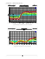
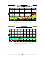
Sample clock jitter can be isolated and measured to a resolution better than 2 psec using a
16,000 point FFT analysis of the 24-bit digital audio output of an A-to-D converter. If, for
instance, a -1 dBFS 10 kHz high purity test tone is connected to the analog input of an A-to-
D converter, sample clock jitter of 16 psec will produce spurious tones (side bands from the
jitter’s phase modulation effect) which have a total energy of -123 dBFS. If the jitter energy
is concentrated at a single frequency, as is often the case, two side bands will be produced,
one on either side of the 10 kHz test tone. Each side band will have an amplitude of -129
dBFS. Although -129 dBFS is an extremely low level, it is still within the resolving ability of
31


