background image

Page 5

R1

R2

R3

CH1

TO CH1

LOAD

FROM

SUPPLY

FROM

SUPPLY

L1

N/L2

L1 N/L2

CH2

TO CH2

LOAD

L1
N/L2

L1 N/L2

FROM

SUPPLY

CH3

TO CH3

LOAD

L1
N/L2

L1 N/L2

R4A

R4

COM

Low

Speed

High

Speed

R4A

L1

L2

COM

N/O

N/C

CH4

240V

2 SPEED

MOTOR

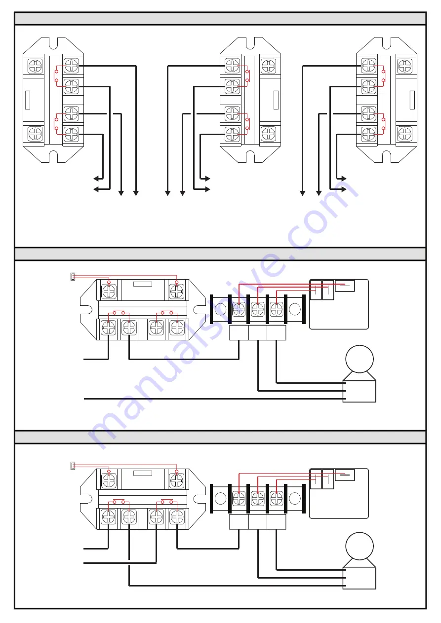
CABLE CONNECTION DETAILS FOR CHANNEL 4 FOR 240V 2 SPEED MOTOR

COM

Low

Speed

High

Speed

R4A

R4

L1

N

COM

N/O

N/C

CH4

CH4A

120V

2 SPEED

MOTOR

CABLE CONNECTION DETAILS FOR CHANNEL 4 FOR 120V 2 SPEED MOTOR

CABLE CONNECTION DETAILS FOR CHANNEL 1, 2 & 3

Содержание PAL Touch-5 Series

Страница 1: ...TALLATION MAINTENANCE INSTRUCTIONS ON THE PCR 5 4 CHANNEL REMOTE CONTROL SYSTEM FEATURES Easy to Install Approved to UL1563 CSA C22 2 No 218 1 13 Pending Remote Control Operation from PCT 5 Transmitter Optional Wi Fi Control from Apple iOS Devices or Android Devices Optional Local Control from BR 04 Module IP65 Wet Location Construction PENDING LIGHTING TM TM ...

Страница 2: ...CR 5 can be fitted with the BR 04 module to provide local control with LED Indication This module can also be hardwired to provide remote control with indication Optional BR 04 Local Control Module IP65 PAL Pool Lighting Channel 5 C h a n n e l 1 4 PAL Mini 4 Loads such as Pumps Blowers Heater Valve Control PAL LED Optics PCR 4 CLASS 2 POWER SUPPLY FOR PAL 4 WIRE LED LIGHTS SUPPLY VOLTAGE 100 240V...

Страница 3: ...it entries at the bottom of the PCR 5 as shown to connect the switch wires to the Power Relays Step 4 The PCR 5 Driver Receiver is factory set to operate with the PCT 5 Transmitter supplied Just fit the 2 x batteries supplied with the PCT 5 and the Transmitter is coded ready to provide Touch control to the system Please refer to the information supplied with the PCT 5 transmitter for full operatin...

Страница 4: ...er 1 2 PVC Conduit 1 2 PVC Conduit Adaptor 1 2 PVC Conduit Adaptor To Power Supply Note Use the 4x Mounting Feet to fasten the enclosure to the wall with the screw set supplied ELECTRONIC POWER SUPPLY 100 240 AC 12V DC DRIVER RECEIVER V CH4 AUX EARTH ACTIVE NEUTRAL E A N COM Low Speed High Speed R1 FZ1 FZ4 FZ2 FZ3 R2 R3 R4 R4A LED 4A Power On Code Setting LED 4CH PCT 5U ON LED ON LED ON LED ON LED...

Страница 5: ...1 N L2 L1 N L2 R4A R4 COM Low Speed High Speed R4A L1 L2 COM N O N C CH4 240V 2 SPEED MOTOR CABLE CONNECTION DETAILS FOR CHANNEL 4 FOR 240V 2 SPEED MOTOR COM Low Speed High Speed R4A R4 L1 N COM N O N C CH4 CH4A 120V 2 SPEED MOTOR CABLE CONNECTION DETAILS FOR CHANNEL 4 FOR 120V 2 SPEED MOTOR CABLE CONNECTION DETAILS FOR CHANNEL 1 2 3 ...

Страница 6: ...e captive trippers to the outer ring position for the entire period that the load is to be turned ON i e fifteen minutes for each tripper on the 24 Hour dial When the tripper is pushed to the inside the switch is in the OFF position OPERATION With the Time Clock programmed and set in Automatic Mode The time clock will switch ON and OFF Channel 4 controlling the pump With the Time Clock OFF Channel...

Страница 7: ...ved When removing the knock outs place a flat blade screwdriver with a 3 16 4mm blade as shown and a light hit with a hammer to the head of the screw driver will allow the Knockout to be removed Alternatively drill location points are located in the centre of each Knock out to allow the use of a hole saw to remove the knockouts IP65 6 7 8 174 0mm 6 7 8 174 0mm 7 1 8 181 0mm 8 7 8 225 0mm 9 1 8 232...

Отзывы: