


SECTION S 12-700-100
223-TVPE
ADAPTER
82-TVPE
CONNECTING
BLOCK
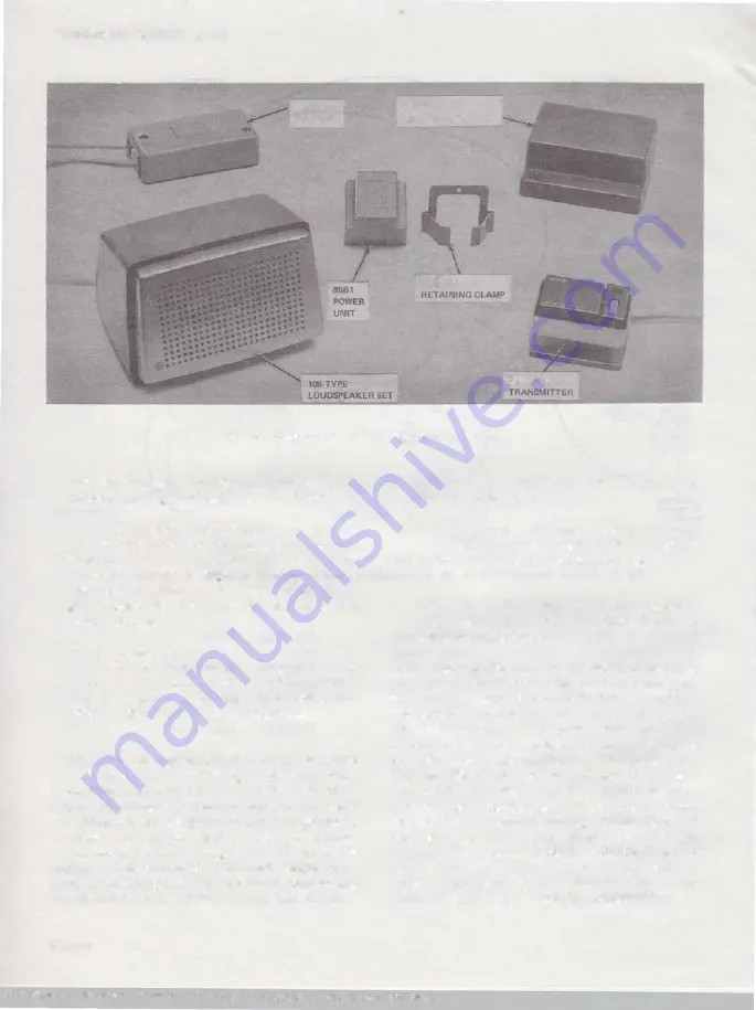
841050818
680-TVPE
Fig. 3-Components of 4A Speakerphone System
This simultaneous transfer of loss and gain
avoids a singing condition while receiving.
(3) When speech is transmitted, the gain of
the transmitter circuit increases to normaL
Simultaneously, the gain of the loudspeaker circuit
lowers to avoid singing as a result of the
increased transmitter gain. The amount of the
gain change depends upon the setting of the
volume controL
(4) A circuit, referred to as a switchguard,
utilizes the voltage in the loudspeaker circuit
to prevent false operation of the switching circuit
from the receive speech output of the loudspeaker
which is picked up by the microphone.
(5) A predetermined voice level is necessary to
switch from the receiving to the transmitting
condition. In the presence of steady room noise,
such as a fan or an air conditioner, a special
circuit, called noise-guard circuit, automatically
raises the required threshold level to prevent
operation of the switching control circuit by the
noise. Talkers should still switch satisfactorily
because they generally increase their speaking
levels under noisy conditions.
Page 4
B.
Radio Frequency Interference (RFI) and/ or Static
Electricity Discharge Protection
2.10
In areas where R F I and/or static electricity
is a problem, install a 680AD (MD) or 680AE
transmitter and a 108AA loudspeaker set.
C.
680A {MD}. 680A 14 (MD}. 680AR {MD}. 680AR 14
(MD}. 680AD {MD) , 680AD14 (MD}. 680AE, or
680AE14 Transmitter
2.11
The transmitter is a small unit incorporating
the microphone, preamplifier, an indicator
lamp, and the operating controls for the speakerphone.
The controls include the ON O R QUIET button,
the O F F button, and the volume controL
The
control button and a stationary button comprise
the color significant portions of the transmitter.
The ON O R QUIET button activates the system
and, if held depressed, disables the microphone so
that the speakerphone user may conduct a private
conversation without the party at the far end
hearing.
The OFF button simply turns off the
system.
The volume control varies the received
sound level, but has no effect on the level of
speech transmitted to the telephone line.
The
indicator lamp lights when the system is on.
BSP 512·700-100-i05_1979-04-Q4.jpg Scanned by Frank Harrell, (Cowboy Frank) Castle Rock, Colorado Feb 16, 2012 23:01:10


