


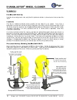

DURABLASTER
®
WHEEL CLEANER
18
Belanger, Inc.® * PO BOX 5470 * Northville, MI 48167-5470 * Ph (248) 349-7010 * Fax (248) 380-9681
1MANUL054
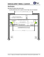
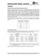
Installation
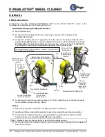
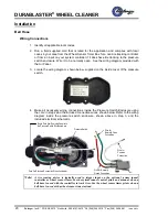
Bell Hose and Wear Strip
Note:
If your system has Tire Tracking from a Main Belanger® Controller, the tire sensing device
connected to your controller should be mounted within 12” of the entrance photo-eye. Not all
controllers have Tire tracking controls. If your controller does not have tire tracking, then place
the bell hose 36” before the DuraBlaster® centerline. A Belanger® Wheel Sensor Timer is also
required.
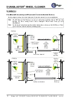
Set up the activation mechanism on the passenger side of the tunnel in front of DuraBlaster®, 36
”
from the center of the DuraBlaster® base tube. Follow the instructions below for details.
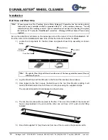
1) Locate the components for the Bell Hose and plastic Wear Strip assembly as shown
below.
108264
1CLAMP373
Note:
The plastic Wear Strip will slow down the wear of the hose against the cement floor as
vehicles roll over it.
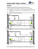
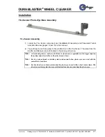
2) Lag the Wear Strip and Floor Mounts to the floor at the locations shown above.
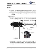
3) Once lagged to the floor, secure the Bell Hose to the two Floor Mounts realizing it will
need to be stretched and cut-to-fit. Secure it into place using the supplied clamps.
The completed assembly should appear as shown below.
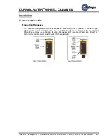
4) The two floor mounts will be secured to the floor. The one in the middle of the tunnel will
have a plug installed in the end and the other one will have a 1/4” push-in tube fitting
installed
5)
Run a field supplied 1/4” poly-flow tube from one of the mounts to the pressure switch.
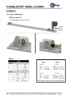
108264 (2):
Floor Mounts
1CLAMP373
(2)
Rubber Bell Hose
Plastic Wear Strip


