


belfuse.com/power-solutions
BCD20021-G Rev AF, 29 November 2021
Page 22 of 26
X Series
375, 500 Watt AC-DC and DC-DC DIN-Rail Converters
© 2021 Bel Power Solutions & Protection
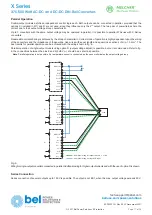
D5: System Volt. Monitor (Battery Deep Discharge)
D5 monitors the output voltage
V
o
(
V
o2
in double-output models) or the lowest admissible voltage of a connected battery (battery
deep discharge). The definition of D5 is similar to D1, but the trigger level is lower. When
V
o
(or
V
o2
) is greater than
V
o low D5
specified in table 17, the D2 signal output is conducting:
V
D5
< 1.5 V,
I
D5 max
< 50 mA.
When
V
o
is lower, the D5 signal output is high impedance (open-collector, max. 58.6 V). In double-output models, D5 monitors
only output 2 (
V
o2
).
In systems without battery support, D5 signals that
V
o
(or
V
o2
) is going to drop below a safe value.
In battery-buffered systems, D5 indicates that the battery has reached its deepest discharge level prior to getting damaged.
The D5 signal can be used for instance to disable loads, save data, or to start a controlled switch-off of running processes.
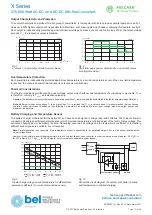
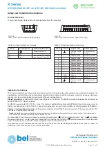
Adjustment of Threshold Levels (D1 or D5)
Pin 7 of the D-SUB connector allows for adjustment of the threshold levels of D1 and D5. Both levels are influenced by the voltage
divider
R
x /
R
y. Resistor
R
x to pin 3 (VCC) lowers the levels, whereas
R
y to pin 1 (GND1) increases them; see fig. 19.
1
2
3
4
5
6
7
8
9
D-SUB (female)
06148b
Rx
Change threshold
Ry
VCC
GND1
D-adj
Fig. 19
Wiring to adjust both threshold levels of option D1 or D5
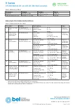
Table 18: Options D1 and D5: Trigger and switch-on levels
Model
Battery
V
Bat
[V]
V
o low D1
V
o low D5
trigger [V]
switch on [V]
trigger [V]
switch on [V]
LXR/LXN1140
12
11.5
12.1
10.5
12.1
LXR/LXN1240
24
23
24.2
21
24.2
LXR/LXN1840
36
34.4
36.3
31.5
36.3
LXR/LXN1740
48
46
48.4
42
48.4
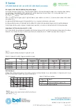
SD: Shutdown
Reduces the output power to approx. 1 W, but the converter is not fully disabled. In a no-load condition,
V
o
drops below 6.2 V; see
fig. 20. In double-output models, only output 2 is influenced.
05175b
3
1
0
0.2
0.4
0.6
0.8
1.2
1
A
5
Output current
V
Output voltage
Table 19: Shutdown conditions
Voltage
V
SD
on
shutdown pin
Result
<0.7 V
Converter disabled (
P
o
approx. 1 W)
≥
2.0 V or open
Converter enabled
Fig. 20
Output voltage versus output current, while the shutdown is
activated (V
i
= V
i nom
).