background image

3


INSTALLATION INSTRUCTION 


Asia-Pacific 

+86 755 298 85888


Europe, Middle East 

+353 61 225 977


North America 

+1


408


785 5200


© 2020 Bel Power Solutions & Protection


BCM.00438_AB


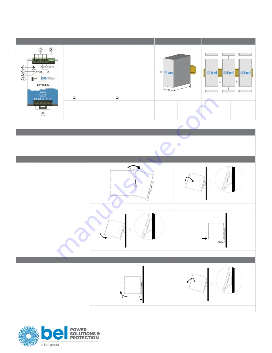
FIG.1 - CONNECTIONS 

FIG.2 - DIMENSIONS 

FIG.3 - DISTANCES 


Just for reference 

(1)


AC/DC input 

(2)


DC output (load) 

(3)


Diagnostic Output  
(dry contact, NC output OK) 

(4)


Green LED: Output OK 

(5)


Red LED: overload 

(6)


Output voltage adjustment 

(7)


Selectable limitation mode  
(Hiccup mode, C.C. mode) 


Input AC Line: 


L1 = Phase 1 


L2 = Phase 2 


L3 = Phase 3 


 = earth ground 

Input DC Line: 


L1 = + Positive DC 


L2 = - Negative DC 


L3 = do not connect 


= earth ground 

Output: 
+ = Positive DC / - = Negative DC / Dry contact = NC 

Dimension 


mm (inc) 

80 (3.15) 

137.5 (5.41) 

127 (5.00) 

Distance 


mm (inc) 

20 (0.8) 

100 (3.9) 


FIG.4 - MOUNTING / DISMOUNTING INSTRUCTIONS 

 
For DIN rail fastening according to IEC 60715 TH35-7.5(-15) 
Mounting as shown in figure, with input terminals on lower side, with suitable cooling and maintaining a proper distance between adjacent devices as specified in the 
Installation Instruction of each family. 


MOUNTING: 


1.


Tilt the unit slightly backwards. 

2.


Fit the unit over the top edge of the rail. 

3.


Slide it downward until it hits the stop. 

4.


Press against the bottom for locking. 


DISMOUNTING: 


1.


Pull down the slide clamp lever 

2.


Tilt the unit upward 

3.


Unhook the unit from the rail


1 & 2 


Содержание LDT960 Series

Страница 1: ...rmeiden schließen Sie das Gerät nicht an oder trennen Sie es nicht ohne vorher die Eingangsspannung abgeschaltet zu haben und warten Sie die Entladung der internen Kondensatoren ab mindestens 1 Minute RISCHIO USTIONI ESPLOSIONE INCENDIO SCOSSA LESIONI GRAVI Non effettuare mai operazioni sulle parti sotto tensione Pericolo di lesioni letali Il contenitore può scottare lasciar quindi raffreddare il ...

Страница 2: ... load With output voltage set to the max value the continuous current x voltage must not exceed the nom power 8 PARALLEL CONNECTION AND REDUNDANCY Power supplies can be connected in parallel to increase power For paralleling for power set the Ilim jumper to C C algorithm Vout must be set uniformly 100 mV on each power supply and the wiring must be symmetrical to ensure an equal current distributio...

Страница 3: ... not connect earth ground Output Positive DC Negative DC Dry contact NC Dimension W D H mm inc 80 3 15 137 5 5 41 127 5 00 Distance A B mm inc 20 0 8 100 3 9 FIG 4 MOUNTING DISMOUNTING INSTRUCTIONS For DIN rail fastening according to IEC 60715 TH35 7 5 15 Mounting as shown in figure with input terminals on lower side with suitable cooling and maintaining a proper distance between adjacent devices ...

Страница 4: ...tection it is strongly recommended to provide external surge arresters SPD according to local regulations FIG 7 INPUT CONNECTIONS AC LINE DC LINE FIG 8 ENVIRONMENT OPERATING TEMPERATURE DERATING 40 C to 70 C 5 95 r H non condensing UL Certified up to 45 C 15 W C over 45 C NOTES Data may change without prior notice in order to improve the product Please refer to the latest version of the Installati...

Отзывы: