


Asia-Pacific
+86 755 298 85888
Europe, Middle East
+353 61 225 977
North America
+1 408 785 5200
© 2017 Bel Power Solutions & Protection
BCG.00966_AA
LDD240-WU
240 W Universal DC-DC Converter
5
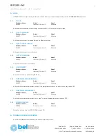
4.2 OUTPUT VOLTAGE PROGRAMMING
LDD240-WU output voltage can be programmed over a range from 4.5V to 55V thanks to the “Output Voltage” menu item, see §4. The
resolution is 10 mV.
While setting the output voltage the screen cycles between integer part (with dot point on) and cents of volts every 3sec. For example, if the
value 24.56 V is set the screen cycles between the following two screens:
Figure 4. Example of 24.56 V setting value shown on display
4.3 CURRENT LIMITATION
LDD240-WU can be set-up with 2 different current limitation algorithms, depending on application. The maximum current delivered by the
device can be limited thanks to the “Output Current (IO)” menu. The maximum output current (Imax) can be limited from 1 A to 11 A (default
10 A) through this menu, see §4. Once the load asks for more current than the programmed Imax the device goes into current limitation
mode; two limitation algorithms are selectable by the user, see §3.3.1 and §3.3.2 for details.
NOTE: To self-protect, the device never delivers higher current than the one specified on the datasheet “Output power limitation curve” and
“Output current limitation curve” charts. This regardless of the Imax setting value.
4.3.1
HICCUP
When LDD240-WU is set up in “Hiccup mode (HU)” the output current is limited at 1.5xImax. When the programmed Imax value is exceeded
a timer is started. If the load current demand is not reduced below Imax within 5 seconds the output is switched off for 10 seconds.
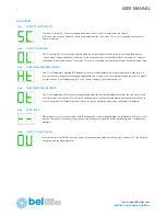
Overload (OL) error message is shown on the display, see §3.6 details. This cycle is then repeated until the load current demand is not
decreased below Imax.
This operating mode is recommended when powering loads requiring high inrush current demands. In case of a direct short circuit on the
output the output is switched off in about 0.2 seconds and kept off for 10 seconds. Short Circuit (SC) error message is shown on the display,
see §3.6 details. This cycle is then repeated until the short circuit is removed.
Note: when “Parallel (PA)” mode is selected the current limitation method is automatically fixed to “Constant Current (CC)” model and it is not
possible to select “Hiccup mode” when “Parallel mode” is selected.
4.3.2
CONSTANT CURRENT
When LDD240-WU is set up in “Constant Current (CC)” the output current is limited at Imax. If the load asks for more current than Imax the
output voltage is progressively decreased to keep the output current regulated at Imax. When the output voltage decreases below 90% of the
programmed output voltage the “DC-OK” relay dry contact opens see §3.5, informing the user that the output voltage is no more regulated.
This operating mode is recommended when powering highly capacitive loads. In case of a direct short circuit on the output the output is
switched off in about 0.2 seconds and kept off for 10 seconds. Short Circuit (SC) error message is shown on the display, see §3.6 details.
This cycle is then repeated until the short circuit is removed.
4.4 OUTPUT ENABLE
The LDD240-WU is provided with a software control allowing to switching ON and OFF the output of the device. This flag is available at
Modbus address 0x1014, see §3.7 for details.
4.5 DC-OK RELAY
A normally open relay is used to indicate that the output voltage is available and regulated. If the output voltage drops below 90% of the
programmed output voltage value.