background image


© BEKA 2019 All rights reserved! 

-38-  

BAL2576_BEKA

_HAMAX_Syste

m

2_0919DE_EN_FR 


8.1.4  Hose connection for version M16 


Assemble the enclosed fittings to the outlets S1 to S3 (fig. 2). 


Tighten the device with two hexagon head screws M16x120 incl. lock washers at the carrier device (120 Nm). 


Connect the hydraulic supply S3 and hydraulic return S2 of the device by a bypass line with the hydraulic system of the carrier 
device. 


Ventilate the device (see chapter 9.3 “Ventilation of the device”). 


Connect the lubricant line to the lubricant connection S1. 


Содержание HAMAX 2

Страница 1: ... 1 BEKA 2019 BAL2576_BEKA_HAMAX_System2_0919DE_EN_FR Originalbetriebs und Montageanleitung Original operating and assembly manual Notice d utilisation original et d entretien ...

Страница 2: ...and assembly manual 28 Notice d utilisation original et d entretien 53 Einbauerklärung für unvollständige Maschinen 78 Declaration of incorporation for partly completed machinery 78 Déclaration d incorporation pour quasi machines 78 Angaben zum Hersteller 80 Details of the manufacturer 80 Détails du fabricant 80 ...

Страница 3: ...3 BEKA 2019 Alle Rechte vorbehalten BAL2576_BEKA_HAMAX_System2_0919DE_EN_FR Stand 09 2019 Originalbetriebs und Montageanleitung ...

Страница 4: ...ge des Geräts 11 8 1 1 Variante Schlauchanschluss bei Ausführung M14 11 8 1 2 Variante Flanschanschluss bei Ausführung M14 11 8 1 3 Anbaumaße Ausführung M14 12 8 1 4 Schlauchanschluss bei Ausführung M16 13 8 1 5 Anbaumaße Ausführung M16 14 8 2 Leitungsmontage 15 9 Inbetriebnahme 15 9 1 Kartusche einschrauben 15 9 2 Kartuschenadapter wechseln 16 9 3 Entlüftung des Gerätes 16 9 4 Entlüftung des Syst...

Страница 5: ... Schalldruckpegel 70dB A Gewicht max 7 kg ohne Kartusche Schmierstoffbehälter Kartusche Kompatible Kartuschen Typ F FU J L R Ra oder S Schmierstoff EP Fette ohne Feststoffanteile oder Meißelpasten von NLGI Kl 000 bis 2 Die Pumpe HAMAX SYSTEM 2 wird nachfolgend als Gerät bezeichnet 2 Schmierstoffe Folgende Meißelpasten sind für die Verwendung im Gerät freigegeben BEKA Meißelpaste Baier Köppel GmbH ...

Страница 6: ... BEKA 2019 Alle Rechte vorbehalten 6 BAL2576_BEKA_HAMAX_System2_0919DE_EN_FR 3 Code ...

Страница 7: ... des Gerätes führen können Wenn auf Besonderheiten aufmerksam gemacht werden soll wird dieser Ausdruck verwendet Direkt am Gerät angebrachte Hinweise müssen unbedingt beachtet und in vollständig lesbarem Zustand gehalten werden 4 2 Personalqualifikation und Personalschulung Das Personal für Bedienung Wartung Inspektion und Montage muss die entsprechende Qualifikation für diese Arbeit aufweisen Zus...

Страница 8: ...lbar nach Abschluss der Arbeiten wieder einzusetzen Entsprechend den einschlägigen behördlichen Bestimmungen müssen umweltgefährdende Medien fachgerecht entsorgt werden Verschmutzte oder kontaminierte Oberflächen sind vor den Wartungsarbeiten zu reinigen hierfür ist Schutzausrüstung zu tragen Beachten Sie hierzu die Daten und Sicherheitsdatenblätter der Schmierstoffhersteller bzw die der Herstelle...

Страница 9: ...nterschritten werden Betreiben Sie das Gerät nie ohne Schmierstoff Eigenmächtige bauliche Veränderungen an dem Gerät sind nicht zulässig Für daraus entstehende Schäden an Personen und Maschinen übernimmt BEKA keinerlei Haftung Zur bestimmungsgemäßen Verwendung gehört auch Dass Sie alle Kapitel und Hinweise in der Betriebsanleitung beachten Dass Sie alle Wartungsarbeiten durchführen Dass Sie alle e...

Страница 10: ... durch Schmierstoffe auch wenn diese bei BEKA einem Labortest unterzogen und freigegeben wurden da schmierstoffbedingte Schäden bspw durch überlagerte falsch gelagerte Schmierstoffe Chargenschwankungen etc im Nachhinein nicht nachvollzogen werden können 7 Transport und Lagerung Benutzen Sie zum Transport geeignete Hebevorrichtungen Das Gerät nicht werfen oder starken Stößen aussetzen Während des T...

Страница 11: ...rzu die beigefügten Zylinderschrauben M4x12 und die Cu Dichtringe 4x8x1 verwenden Bei diesem Anwendungsfall sind die O Ringe 9x2 5 die Verschlussschrauben G1 4 und die Dichtringe 13x18x1 5 nicht nötig Für den Schmierstoffanschluss S1 Abb 1 ist eine der mitgelieferten Einschraubverschraubung zu montieren Der Schmierstoffanschluss S1 kann wahlweise auch an einen der alternativen Schmierstoffanschlüs...

Страница 12: ... BEKA 2019 Alle Rechte vorbehalten 12 BAL2576_BEKA_HAMAX_System2_0919DE_EN_FR 8 1 3 Anbaumaße Ausführung M14 Abb 1 Typ Maß H in mm S 300 L 265 F 310 J 285 FU 325 R 300 Ra 290 ...

Страница 13: ...3 Abb 2 montieren Gerät mit zwei Sechskantschrauben M16x120 inkl Sicherungsscheiben am Trägergerät festschrauben 120 Nm Hydraulik Zulauf S3 und Hydraulik Rücklauf S2 des Geräts durch eine Bypassleitung mit dem Hydrauliksystem des Trägergerätes verbinden Gerät entlüften siehe Kapitel 9 3 Entlüftung des Gerätes Schmierstoffleitung an den Schmierstoffanschluss S1 anschließen ...

Страница 14: ... BEKA 2019 Alle Rechte vorbehalten 14 BAL2576_BEKA_HAMAX_System2_0919DE_EN_FR 8 1 5 Anbaumaße Ausführung M16 Abb 2 Typ Maß H in mm S 300 L 265 F 310 J 285 FU 325 R 300 Ra 290 ...

Страница 15: ... geeignet sind und die Anforderungen der jeweiligen Einsatzbedingungen erfüllen Schmierstoffangaben des Maschinenherstellers beachten Sicherheitsdatenblatt des Schmierstoffherstellers beachten Fließverhalten des Schmierstoffes ändert sich mit der Betriebstemperatur Beim Wechsel der Kartuschen auf äußerste Sauberkeit achten Die im Adapter befindlichen O Ringe Abb 3 Pos 1 2 müssen vor dem Einbau der...

Страница 16: ... wieder mit einem Innensechskantschlüssel SW 4 festziehen 6 Nm Abb 5 9 3 Entlüftung des Gerätes Das Gerät muss entlüftet werden wenn es erstmalig in Betrieb genommen wird oder wenn es längere Zeit Luft angesaugt hat und nun nicht mehr fördert Gerät über den Schmiernippel Abb 5 Pos 3 so lange mit Schmierstoff befüllen bis am Schmierstoffauslass luftblasenfreier Schmierstoff austritt Hierfür kann ei...

Страница 17: ...dermenge Einschrauben der Einstelldrossel verringert die Durchflussmenge und vermindert somit die Fördermenge Das untenstehende Diagramm Abb 8 zeigt Richtwerte für die Einstellung der Fördermenge Die Einstellung der Exzenterumdrehungen Fördermenge des Geräts erfolgt mittels Einstelldrossel wobei der Hydrauliköldurchfluss individuell an jedem Gerät vorgenommen werden muss Falls die notwendige Förde...

Страница 18: ...rstoffsystems ist im Gerät ein Druckbegrenzungsventil DBV Abb 9 Pos 3 eingebaut das bei 280 bar öffnet Die Auslassöffnung Abb 9 Pos 1 des DBV befindet sich gegenüber der Kartuschenaufnahme Als Vorratsbehälter kommen transparente Kunststoffkartuschen Abb 9 Pos 7 zum Einsatz Durch ein Adaptersystem können verschiedene Kartuschentypen verwendet werden Die Fettstandskontrolle erfolgt optisch über die ...

Страница 19: ...ngen an die Exzentereinheit Abb 10 Pos 4 überträgt Die Exzentrizität bewirkt den Saug und Druckhub des Förderkolbens vom Pumpenelement Abb 10 Pos 3 Ein integriertes Rückschlagventil Abb 10 Pos 2 verhindert ein Zurücksaugen des Schmierstoffes Über den Druckkanal D wird der Schmierstoff zu den verschiedenen Auslässen gefördert die je nach Einbauort bzw lage offen oder geschlossen sind Als Vorratsbeh...

Страница 20: ...itt von Schmierstoff unter hohem Druck kommen Haben sich durch Leckagen Schmierstoffpfützen gebildet sind diese sofort zu beseitigen 11 2 Kartuschenwechsel Befindet sich der Kartuschenfolgekolben Abb 12 Pos 3 am Boden der Kartusche ist diese zu erneuern Die Kontrolle des Folgekolbens ist durch das Sichtfenster Abb 12 Pos 4 im Pumpengehäuse bzw im Adapter erleichtert Beim Wechseln der Kartusche ist...

Страница 21: ...das Pumpengehäuse einlegen und mit der Verschlussschraube und Cu Dichtring Abb 13 Pos 3 fixieren Abb 13 1 Blende 2 Siebkorb 3 Cu Dichtring 4 O Ring 5 Druckstück 6 Verschlussschraube 11 4 Druckbegrenzungsventil wechseln Zur Absicherung des Schmierstoffkreislaufs ist im Gerät ein Druckbegrenzungsventil Abb 14 Pos 2 integriert Dieses öffnet ab einem Schmierstoffdruck von 280 bar Zum Austausch des Dru...

Страница 22: ...e Pumpenelement schrauben Die Passfeder Abb 15 Pos 3 muss sich in der zugehörigen Nut des Pumpenelementes befinden Bei der Montage des neuen Pumpenelements darauf achten dass kein Schmutz in das Gerät gelangt Pumpenelement so in die Aufnahmebohrung stecken dass die Passfeder in der Nut des Pumpengehäuses einrastet Den auf der Arretierungsschraube befindlichen O Ring vor der Montage leicht einfette...

Страница 23: ...sel verschlossen Einstelldrossel ca 1 1 2 Umdrehungen gegen den Uhrzeigersinn drehen und Ölzufuhr einschalten Nach Funktionstest Einstelldrossel wieder einstellen Hydromotor defekt Hydromotor tauschen Gegendruck im Rücklauf zu hoch max 30 bar Hydrauliksystem prüfen Gerät fördert keinen Schmierstoff Exzenterwelle dreht jedoch Luftblase in der Kartusche Kartusche aus dem Adapter herausschrauben Auf ...

Страница 24: ...Kontrolle der Sichtfenster möglich Auch ist die Einstelldrossel zur Regulierung der Durchflussmenge weiter erreichbar Abb 16 nur für Ausführung M14 Artikel Nr Schutzgehäuse inkl Befestigungsmaterial 10104301 Schutzgehäuse ohne Befestigungsmaterial 10104212 Abb 17 für Ausführung M14 und M16 Artikel Nr Schutzgehäuse ohne Befestigungsmaterial 10102722 ød 15 5 Ausführung M14 Schutzgehäuse ohne Befesti...

Страница 25: ...stellt werden Typ Fettmenge Schmierstoff Art Nr Kartusche Art Nr Kartuschenadapter S 400 g EP2 Fett 10104365 10101746 BEKA Meißelpaste 10104366 F 500 g EP2 Fett 10102638 10101979 Fuchs Meißelpaste 10102639 BEKA Meißelpaste 10119916 L BEKA Meißelpaste 10135218 10101736 J 10116930 FU 10101717 R 10134623 Ra 2576GK0008 Fett Kartuschen Kartuschenadapter Typ S Standard Abb 18 Abb 19 Typ F Abb 20 Abb 21 ...

Страница 26: ... BEKA 2019 Alle Rechte vorbehalten 26 BAL2576_BEKA_HAMAX_System2_0919DE_EN_FR Typ J Abb 24 Abb 25 Typ FU Abb 26 Abb 27 Typ R Abb 28 Abb 29 Typ Ra Abb 30 Abb 31 ...

Страница 27: ...rage erhältlich Bezeichnung Artikel Nr Pumpenelement PE 120FH 10123263 Hydromotor 10106611 Einstelldrossel 10102314 Druckbegrenzungsventil 10103325 Filter komplett 10107851 Schneckenwelle 10123201 Exzentereinheit 10123212 Getriebedeckel 10123171 Sichtfenster 10100048 17 Maßzeichnung Alle Maße sind den Zeichnungen in den Kapiteln 8 1 3 Anbaumaße Ausführung M14 und 8 1 5 Anbaumaße Ausführung M16 zu ...

Страница 28: ... BEKA 2019 All rights reserved 28 BAL2576_BEKA_HAMAX_System2_0919DE_EN_FR Revision 09 2019 Original operating and assembly manual ...

Страница 29: ...Hose connection variant for version M14 36 8 1 2 Flange connection variant for version M14 36 8 1 3 Attachment dimensions of version M14 37 8 1 4 Hose connection for version M16 38 8 1 5 Attachment dimensions of version M16 39 8 2 Connection of lines 40 9 Start up 40 9 1 Screw in cartridge 40 9 2 Change of the cartridge adapter 41 9 3 Ventilation of the device 41 9 4 Ventilation of the system 41 9...

Страница 30: ... stroke adjustable with adjusting throttle General Sound pressure level 70dB A Weight max 7 kg without cartridge Lubricant reservoir cartridge Compatible cartridges type F FU J L R Ra or S Lubricant EP greases without solid content or chisel pastes from NLGI cl 000 to 2 The pump HAMAX SYSTEM 2 is subsequently called a device 2 Lubricants The following chisel pastes are released for the use in this...

Страница 31: ...31 BEKA 2019 All rights reserved BAL2576_BEKA_HAMAX_System2_0919DE_EN_FR 3 Code ...

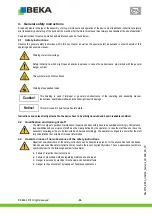
Страница 32: ...age This term is used to point out particular details Instructions and notes directly attached to the device have to be strictly observed and kept in readable condition 4 2 Qualification and training of staff The staff in charge of operation maintenance inspection and assembly have to be qualified accordingly Competence responsibilities and supervision of staff must be clearly defined by the opera...

Страница 33: ...mmediately after completion of the work Environmentally hazardous media must be disposed of professionally and according to the relevant legal provisions Polluted and contaminated surfaces have to be cleaned before maintenance Please wear protective equipment to that purpose See the lubricant manufacturers safety data sheets hereto respectively the data sheets provided by the manufacturers of auxi...

Страница 34: ...tioned in the technical data Never operate the device without lubricant Unauthorized modifications of the device are not permitted BEKA is not liable for personal injury or damage of machine resulting thereof The intended use also includes paying attention to all chapters and notes in the operating and assembly manual carrying out all maintenance work observing all relevant instructions for work s...

Страница 35: ...claims for any damage caused by lubricants even though those have been laboratory tested and released by BEKA as such damage e g by over stored or incorrectly stored lubricants batch fluctuations etc cannot be verified or reconstructed later 7 Transport and storage Use suitable lifting devices for transport Do not throw the device or expose it to shocks Secure the device against toppling down or s...

Страница 36: ...closed head cap screws M4x12 and the CU sealing rings 4x8x1 for this In this application case the O rings 9x2 5 the screw plugs G1 4 and the sealing rings 13x18x1 5 are unnecessary For the lubricant connection S1 fig 1 assemble one of the supplied male stud couplings The lubricant connection S1 can optionally also be assembled to one of the alternative lubricant connections S4 to S6 For this the s...

Страница 37: ...37 BEKA 2019 All rights reserved BAL2576_BEKA_HAMAX_System2_0919DE_EN_FR 8 1 3 Attachment dimensions of version M14 Fig 1 Type Dimension H in mm S 300 L 265 F 310 J 285 FU 325 R 300 Ra 290 ...

Страница 38: ...3 fig 2 Tighten the device with two hexagon head screws M16x120 incl lock washers at the carrier device 120 Nm Connect the hydraulic supply S3 and hydraulic return S2 of the device by a bypass line with the hydraulic system of the carrier device Ventilate the device see chapter 9 3 Ventilation of the device Connect the lubricant line to the lubricant connection S1 ...

Страница 39: ...39 BEKA 2019 All rights reserved BAL2576_BEKA_HAMAX_System2_0919DE_EN_FR 8 1 5 Attachment dimensions of version M16 Fig 2 Type Dimension H in mm S 300 L 265 F 310 J 285 FU 325 R 300 Ra 290 ...

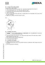
Страница 40: ...ulfill the requirements of the respective operating conditions Observe the lubricant information of the machine manufacturer Observe the safety data sheet of the lubricant manufacturer The flow behavior of the lubricant changes with the operating temperature Ensure utmost cleanliness when changing the cartridge The O rings fig 3 pos 1 2 in the adapter must be lightly greased before assembly of the...

Страница 41: ...ten the four fastening screws with an Allen key AF 4 6 Nm Fig 5 9 3 Ventilation of the device The device must be ventilated when it is initially operated or when it has sucked in air for a longer period of time and no longer delivers lubricant Fill the device with lubricant via the zerk fig 5 pos 3 until bubble free lubricant escapes from the lubricant outlet A standard hand lever grease gun can b...

Страница 42: ...y rate The flow rate decreases by screwing in the adjusting throttle and thus decreases the delivery rate The diagram below fig 8 shows standard values for the setting of the delivery rate The eccentric revolutions delivery rate of the device are set via adjusting throttle whereby the hydraulic oil flow must be adjusted individually at each device If the required delivery rate is unknown you can a...

Страница 43: ...limiting valve PLV fig 9 pos 3 which opens at 280 bar is installed in the device to protect the lubricant system The outlet opening fig 9 pos 1 of the PLV is opposite the cartridge holder Transparent plastic cartridges fig 9 pos 7 are used as storage reservoirs Different cartridge types can be used because of an adapter system The grease level is controlled visually via the position of the visible...

Страница 44: ...g 10 pos 4 The eccentricity effects the suction and pressure stroke of the delivery piston of the pump element fig 10 pos 3 An integrated non return valve fig 10 pos 2 prevents that the lubricant is sucked back The lubricant is delivered to the different outlets via the pressure channel D The outlets are either open or closed depending on the installation location or position Different cartridge t...

Страница 45: ... pressure Remove possible puddles of lubricant immediately 11 2 Cartridge change Renew the cartridge when the cartridge follow up piston fig 12 pos 3 is on the bottom of the cartridge The control of the follow up piston is easier because of the inspection window fig 12 pos 4 in the pump housing or in the adapter Always ensure cleanliness when changing the cartridge Unscrew the cartridge from the d...

Страница 46: ...ece into the pump housing and fixate them with the screw plug and Cu sealing ring fig 13 pos 3 Fig 13 1 Orifice 2 Strainer basket 3 Cu sealing ring 4 O ring 5 Pressure piece 6 Screw plug 11 4 Change of the pressure limiting valve In order to protect the lubricant circuit a pressure limiting valve is integrated in the device fig 14 pos 2 It opens from a lubricant pressure of 280 bar Proceed as foll...

Страница 47: ... element into the new pump element The feather key fig 15 pos 3 must be in the corresponding groove of the pump element Make sure that no dirt enters the device at the assembly of the new pump element Insert the pump into the mounting hole so that the feather key snaps in the groove of the pump housing Lightly grease the O ring which is located on the interlock screw before assembly The pump eleme...

Страница 48: ...losed Turn adjusting throttle approx 1 revolutions counter clockwise and switch off oil supply Switch adjusting throttle on again after functional test Hydro motor defective Exchange hydro motor Counter pressure in return too high max 30 bar Check hydraulic system Device delivers no lubricant however eccentric shaft rotates Air bubble in the cartridge Unscrew cartridge from adapter Apply pressure ...

Страница 49: ...indows The adjusting throttle can also still be reached to regulate the flow rate Fig 16 only for version M14 Article no Protective housing incl fastening material 10104301 Protective housing without fastening material 10104212 Fig 17 for version M14 and M16 Article no Protective housing without fastening material 10102722 ød 15 5 version M14 Protective housing without fastening material 080080226...

Страница 50: ...e Grease quantity Lubricant Art no cartridge Art no cartridge adapter S 400 g EP2 grease 10104365 10101746 BEKA chisel paste 10104366 F 500 g EP2 grease 10102638 10101979 Fuchs chisel paste 10102639 BEKA chisel paste 10119916 L BEKA chisel paste 10135218 10101736 J 10116930 FU 10101717 R 10134623 Ra 2576GK0008 Grease cartridges Cartridge adapters Type S Standard Fig 18 Fig 19 Type F Fig 20 Fig 21 ...

Страница 51: ...51 BEKA 2019 All rights reserved BAL2576_BEKA_HAMAX_System2_0919DE_EN_FR Type J Fig 24 Fig 25 Type FU Fig 26 Fig 27 Type R Fig 28 Fig 29 Type Ra Fig 30 Fig 31 ...

Страница 52: ...tion Article no Pump element PE 120FH 10123263 Hydro motor 10106611 Adjusting throttle 10102314 Pressure limiting valve 10103325 Filter complete 10107851 Worm shaft 10123201 Eccentric unit 10123212 Gear cover 10123171 Inspection window 10100048 17 Dimensional drawing Please refer to the drawings in chapters 8 1 3 Attachment dimensions of version M14 and 8 1 5 Attachment dimensions of version M16 f...

Страница 53: ...53 BEKA 2019 Tous droits réservés BAL2576_BEKA_HAMAX_System2_0919DE_EN_FR Version 09 2019 Notice d utilisation original et d entretien ...

Страница 54: ... tuyau flexible pour la version M14 61 8 1 2 Variante à raccordement par bride pour la version M14 61 8 1 3 Dimensions de montage pour la version M14 62 8 1 4 Raccord de tuyau flexible pour la version M16 63 8 1 5 Dimensions de montage pour la version M16 64 8 2 Montage de conduite 65 9 Mise en service 65 9 1 Vissage de la cartouche 65 9 2 Remplacement de l adaptateur de cartouche 66 9 3 Purge de ...

Страница 55: ...e de courses réglable avec régulateur de débit Généralités Niveau de pression acoustique 70 dB A Poids max 7 kg sans cartouche Réservoir de lubrifiant Cartouche Cartouches compatibles Type F FU J L R Ra ou S Lubrifiant Graisses EP sans particules solides ni pâtes à burin de NLGI classe 000 à 2 La pompe HAMAX SYSTEM 2 est ci après dénommée l appareil 2 Lubrifiants Les pâtes à burin suivantes sont a...

Страница 56: ... BEKA 2019 Tous droits réservés 56 BAL2576_BEKA_HAMAX_System2_0919DE_EN_FR 3 Code ...

Страница 57: ...ons de travail les cycles d opération imposés etc ne sont pas exactement ou pas du tout suivis Ce terme est utilisé s il y a lieu d attirer l attention sur des particularités Les consignes indiquées directement au système doivent absolument être suivies et maintenues dans un état permettant leur lecture complète 4 2 Qualification et formation du personnel Le personnel prévu pour commander entreten...

Страница 58: ...s substances dangereuses pour l environnement doivent être éliminées de manière appropriée Les surfaces encrassées ou contaminées doivent être nettoyées avant les travaux de maintenance pour ce faire le port de l équipement de protection est impératif Se référer aux fiches techniques et de sécurité des fabricants de lubrifiants et le cas échéant à celles des fabricants de produits auxiliaires et c...

Страница 59: ...s être dépassées ou pas atteignent N utilisez jamais l appareil sans lubrifiant Une transformation arbitraire du système à circulation est interdite BEKA ne prend pas la responsabilité pour des dommages aux personnes et machines L utilisation conformément à la destination est Faites attention aux détails dans cette notice d utilisation La réalisation de toutes travaux d entretien Respectez toutes ...

Страница 60: ...lubrifiants même si lesquelles étaient testées et approuvées par un laboratoire parce que des dommages en raison de la lubrifiant par exemple des lubrifiants superposés par stockage faux ne peuvent pas être comprend ultérieurement 7 Transport et stockage Utilisez un élévateur approprié pour transport Ne jamais jeter ou heurter violemment l appareil Durant le transport l appareil doit être assuré c...

Страница 61: ... tête cylindrique M4x12 fournies et les bagues d étanchéité en cuivre 4x8x1 Pour ce cas d application les joints toriques 9x2 5 les vis de fermeture G1 4 et les joints d étanchéité 13x18x1 5 ne sont pas nécessaires Pour le raccord de lubrifiant S1 fig 1 un des raccords vissés fournis doit être monté Le raccord de lubrifiant S1 peut également être monté sur l un des raccords de lubrifiant alternati...

Страница 62: ... BEKA 2019 Tous droits réservés 62 BAL2576_BEKA_HAMAX_System2_0919DE_EN_FR 8 1 3 Dimensions de montage pour la version M14 Fig 1 Type Dimension H en mm S 300 L 265 F 310 J 285 FU 325 R 300 Ra 290 ...

Страница 63: ... à S3 fig 2 Visser l appareil sur le support à l aide de deux vis hexagonales M16x120 avec rondelles de sécurité 120 Nm Raccorder l entrée hydraulique S3 et le retour hydraulique S2 de l appareil au système hydraulique du support par une conduite de dérivation Purger l appareil voir chapitre 9 3 Purge de l appareil Raccorder la conduite de lubrifiant au raccord de lubrifiant S1 ...

Страница 64: ... BEKA 2019 Tous droits réservés 64 BAL2576_BEKA_HAMAX_System2_0919DE_EN_FR 8 1 5 Dimensions de montage pour la version M16 Fig 2 Type Dimension H en mm S 300 L 265 F 310 J 285 FU 325 R 300 Ra 290 ...

Страница 65: ...sés et qu ils répondant aux exigences des conditions d utilisation respectives Respecter les indications sur les lubrifiants du fabricant de la machine Respecter les fiches de données de sécurité du fabricant du lubrifiant La fluidité du lubrifiant change avec la température de service Lors du remplacement des cartouches veiller à ce que les cartouches soient d une propreté extrême Les joints tori...

Страница 66: ... une clé Allen SW 4 6 Nm Fig 5 9 3 Purge de l appareil L appareil doit être purgé lorsqu il est mis en service pour la première fois ou lorsqu il a aspiré de l air pendant une longue période et qu il ne convoie plus maintenant Remplir l appareil de lubrifiant par le graisseur fig 5 pos 3 jusqu à ce que du lubrifiant sans bulles d air sorte par la sortie du lubrifiant Une presse à graisse à levier ...

Страница 67: ...la quantité de débit baisse et donc également la quantité de convoyage Le diagramme ci dessous fig 8 indique les valeurs de référence pour le réglage de la quantité de convoyage Les tours de l excentrique quantité de convoyage de l appareil sont réglés au moyen d un régulateur de débit dont le débit d huile hydraulique doit être réglé individuellement pour chaque appareil Si la quantité de convoya...

Страница 68: ...lubrifiant une vanne de limitation de pression DBV fig 9 pos 3 est installée dans l appareil s ouvrant à 280 bars L ouverture de sortie fig 9 pos 1 du DBV se trouve en face du support de cartouche Des cartouches en plastique transparentes fig 9 pos 7 sont utilisées comme récipients de réserve Différents types de cartouches peuvent être utilisés avec un système d adaptateur Le niveau de graisse est...

Страница 69: ...e fig 10 pos 4 L excentricité provoque la course d aspiration et de refoulement du piston de convoyage de l élément de pompe fig 10 pos 3 Une vanne anti retour intégrée fig 10 pos 2 empêche l aspiration du lubrifiant Le lubrifiant est convoyé par le canal de pression D vers les différentes sorties qui sont ouvertes ou fermées en fonction du lieu ou de la position de montage Différents types de car...

Страница 70: ...Si des flaques de lubrifiants se sont formées dû à des fuites elles doivent être immédiatement éliminées 11 2 Remplacement de la cartouche Si le piston suiveur de la cartouche fig 12 pos 3 est situé au fond de la cartouche il doit être remplacé Le piston suiveur peut être contrôlé simplement par la fenêtre de visualisation fig 12 pos 4 dans le carter de la pompe ou dans l adaptateur Lors du rempla...

Страница 71: ... fermeture et la bague d étanchéité en cuivre fig 13 pos 3 Fig 13 1 Plaque à orifice 2 Panier de tamis 3 Bague d étanchéité en cuivre 4 Joint torique 5 Pièce de pression 6 Vis de fermeture 11 4 Remplacement de la vanne de limitation de pression Une vanne de limitation de pression fig 14 pos 2 est intégrée dans l appareil pour protéger le circuit de lubrifiant Cette dernière s ouvre à partir d une ...

Страница 72: ...ent de pompe La clavette fig 15 pos 3 doit se trouver dans la rainure correspondante de l élément de pompe Lors du montage du nouvel élément de pompe veiller à ce qu aucune saleté ne pénètre dans l appareil Insérer l élément de pompe dans le perçage du support de manière à ce que la clavette s engage dans la rainure du carter de la pompe Graisser légèrement le joint torique de la vis de blocage av...

Страница 73: ...uile Après la fonction régler à nouveau le régulateur de débit Moteur hydraulique défectueux Remplacer le moteur hydraulique Contre pression dans le retour trop élevé max 30 bars Vérifier le système hydraulique L appareil ne convoie pas le lubrifiant mais l arbre excentrique tourne Bulle d air dans la cartouche Dévisser la cartouche de l adaptateur Appliquer une pression manuellement sur le piston...

Страница 74: ...sation Le régulateur de débit peut également être atteint pour la régulation de la quantité de débit Fig 16 uniquement pour la version M14 N d article Carter de protection avec matériel de fixation 10104301 Carter de protection sans matériel de fixation 10104212 Fig 17 pour les versions M14 et M16 N d article Carter de protection sans matériel de fixation 10102722 ød 15 5 version M14 Carter de pro...

Страница 75: ...nge Type Quantité de graisse Lubrifiant N d art Cartouche N d article Adaptateur de cartouche S 400 g Graisse EP2 10104365 10101746 BEKA pâtes à burin 10104366 F 500 g Graisse EP2 10102638 10101979 Fuchs pâtes à burin 10102639 BEKA pâtes à burin 10119916 L BEKA pâtes à burin 10135218 10101736 J 10116930 FU 10101717 R 10134623 Ra 2576GK0008 Cartouches de graisse Adaptateurs de cartouches Type S Sta...

Страница 76: ... BEKA 2019 Tous droits réservés 76 BAL2576_BEKA_HAMAX_System2_0919DE_EN_FR Type J Fig 24 Fig 25 Type FU Fig 26 Fig 27 Type R Fig 28 Fig 29 Type Ra Fig 30 Fig 31 ...

Страница 77: ...ticle Élément de pompe PE 120FH 10123263 Moteur hydraulique 10106611 Régulateur de débit 10102314 Vanne de limitation de pression 10103325 Filtre complet 10107851 Arbre à vis sans fin 10123201 Unité excentrique 10123212 Couvercle de la transmission 10123171 Fenêtre de visualisation 10100048 17 Dessin à l échelle Toutes les dimensions peuvent être tirées des dessins des chapitres 8 1 3 Dimensions d...

Страница 78: ...EKA 2019 78 BAL2576_BEKA_HAMAX_System2_0919DE_EN_FR Einbauerklärung für unvollständige Maschinen Declaration of incorporation for partly completed machinery Déclaration d incorporation pour quasi machines ...

Страница 79: ... 79 BEKA 2019 BAL2576_BEKA_HAMAX_System2_0919DE_EN_FR ...

Страница 80: ...50 POSTFACH 1320 91253 PEGNITZ Bayern Germany http www beka lube de E Mail beka beka lube de beka beka max de Änderungen vorbehalten Für Irrtümer technische Fehler und Druckfehler wird keine Haftung übernommen Subject to alterations We do not accept liability for errors technical mistakes and misprints Sous réserve de modifications BEKA n assume aucune responsabilité pour les confusions les erreur...

Отзывы: