background image

6

5.

INSTALLATION

5.1

Location

The appropriate model BR323AL or BR323SS
should be chosen depending on the severity of
the environment.  The BR323AL is housed in an
epoxy painted aluminium enclosure and the
BR323SS in a stainless steel enclosure suitable
for marine applications. Both provide IP66 and
NEMA Type 4X protection.

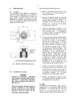
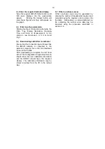
Fig 5  BR323AL & BR323SS dimensions

5.2

Installation procedure

WARNING

Installation of a BR323AL or BR323SS
loop powered indicator should only be
performed in a potentially hazardous
area when an explosive atmosphere is
NOT present.

Ensure that glands, blanking plugs or
conduit connected to the indicator
have the same thread as the indicator
enclosure, which is shown on the
instrument certification label.

Recommended installation procedure:

a.

Remove the flameproof enclosure cover
that contains the viewing window by
rotating anticlockwise.

b.

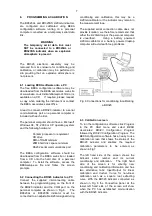
Remove the BR323 electronic assembly
from the enclosure by gently squeezing the
retaining clip and pulling – see Fig 1.   If
necessary remove the screw securing the
earthing wire connecting the electronic
assmebly to the enclosure.

c.  Install the flameproof enclosure in the

required position and secure using the two
M10 mounting slots.   The flameproof
enclosure should be earthed as specified
by the local code of practice.

d.

Fit the required flameproof certified glands
or blanking plugs with the correct thread
into the two entries in the enclosure.
Instruments can have M20 x 1.5 threads
(M suffix on producr number) or ½ inch
NPT entries (N suffix on product number).
The instrument enclosure thread is shown
on the instrument certification label.   The
installation must be as specified by the
manufacturer of the certified gland or
blanking plug and comply with the local
code of practice.   Alternatively, correctly
threaded metal conduit may be used with
a flameproof certified compound filled
stopping box at each of the two entries.
Installation must be as specified by the
manufacturer of the stopping box and
comply with the local code of practice.

e.  Position the electronic assembly in the

flameproof enclosure and connect the two
input terminals as shown in Figs 1 and 4.
If removed, the earthing cable should be
reconnected between the electronic
assembly and the flameproof enclosure.

f.  Replace the flameproof enclosure cover

by rotating clockwise and tighten until the
sealing gasket is compressed.

5.3   EMC

The BR323AL and BR323SS comply with the
requirements of the European EMC Directive
89/336/EEC.  For specified immunity all wiring
should be in screened twisted pairs, with the
screens earthed at one point in the safe area.

Содержание BR323AL

Страница 1: ...Issue 3 1 st July 2008 BR323AL and BR323SS Flameproof Loop powered field mounting indicators Issue 3 ...

Страница 2: ...bration screen 6 4 Linear calibration 6 5 Non linear calibration 6 6 Square root extraction 7 Maintenance 7 1 Fault finding during commissioning 7 2 Fault finding after commissioning 7 3 Servicing 7 4 Routine maintenance 7 5 Guarantee 7 6 Customer comments 8 Accessories 8 1 Pipe mounting kit 8 2 Tag strip 8 3 Tag plate Appendix 1 FM Approval for use in the USA Appendix 2 CSA Approval for use in Ca...

Страница 3: ...lectronic assembly which is common to both the BR323AL and the BR323SS Both instruments have been certified flameproof and comply with the European ATEX Directive 94 9 EC They also have Factory Mutual explosion proof and dust ignition proof approval For use in Canada the BR323SS which is housed in a stainless steel enclosure has CSA explosion proof component approval Note The BR323AL which has an ...

Страница 4: ...ification of T1 450 o C T2 300 o C T3 200 o C T4 135 o C T5 100 o C T6 85 o C At ambient temperatures between 20 and 60 o C This allows both models to be installed in most hazardous areas and to be used with most common industrial gases This manual describes installations in flammable gas atmospheres which conform with EN60079 Part14 Electrical Installation in Hazardous Areas When designing system...

Страница 5: ...um enclosure BR323SS which has a stainless steel enclosure Fig 3 Certification Information Labels 4 SYSTEM DESIGN FOR USE IN HAZARDOUS AREAS BR323AL and BR323SS indicators may be connected in series with any 4 20mA current loop having a maximum supply voltage of 30V dc and a maximum current of less than 110mA It is only necessary to ensure that the loop can support the additional 2 3V drop introdu...

Страница 6: ...ots The flameproof enclosure should be earthed as specified by the local code of practice d Fit the required flameproof certified glands or blanking plugs with the correct thread into the two entries in the enclosure Instruments can have M20 x 1 5 threads M suffix on producr number or inch NPT entries N suffix on product number The instrument enclosure thread is shown on the instrument certificati...

Страница 7: ... indicator to a PC Connect the supplied interconnecting cable between the programming plug on the front of the BR323 indicator and the COM port on the personal computer as shown in Fig 6 The BR323AL or BR323SS indicator must be connected to an adjustable 4 20mA signal during conditioning and calibration this may be a 4 20mA calibrator or the indicator may remain in the measurement loop The supplie...

Страница 8: ...e indicator after the decimal point None One Two or Three digits may be selected alternatively selecting Auto instructs the indicator to display the maximum number of digits possible after the decimal point which will vary as the indicator display changes Note Display Resolution does not affect the Configuration Programme Screen that always shows a fixed number of digits after the decimal point 6 ...

Страница 9: ...323 should have the required display The calibration information may be stored or printed from the PC in the normal way 6 5 Non linear calibration The BEKA configuration software enables non linear functions to be downloaded to a BR323 indicator Any curve that continuously increases or decreases with between 2 and 128 breakpoints may be used 6 6 Square root extraction Probably the most common non ...

Страница 10: ...ws that the BR323 indicator is connected to the personal computer then click the download arrow on the toolbar After downloading is complete the left hand side of the Configuration Programme Screen should show the new calibration information and the BR323 should have the required display The calibration information may be stored or printed from the PC in the normal way 6 7 Other non linear curves ...

Страница 11: ...intenance should only be performed in a potentially hazardous area when an explosive atmosphere is not present If a BR323AL or BR323SS fails after it has been functioning correctly the following procedure should be followed Symptom Cause Solution No display No power Check that a and no volts supply current is flowing in between ve the loop ve terminals Unstable 4 20mA input Check loop supply displ...

Страница 12: ...3SS indicators to be mounted onto any pipe with an outside diameter up to 50mm 8 2 Tag strip The BR323AL and BR323SS can be supplied with tag or applicational information thermally printed onto a polyester strip secured to the instrument mounting bracket The following can be accommodated 1 row of 36 alphanumeric characters 1 8mm high and 1 row of 18 alphanumeric characters 2 6mm high 8 3 Tag plate...

Страница 13: ...66 Dust Ignitionproof T6 40 o C to 60 o C Divisions 1 or 2 Class II or III Gas groups E F G NEMA Type 4X IP66 APPENDIX 2 CSA approval for use in Canada CAUTION The CSA Approval only applies to the BR323SS stainless steel enclosure the BR323AL aluminium enclosure is not CSA Approved A2 1 CSA Approval For installations in the Canada the BR323SS enclosure has explosion proof CSA component Approval Co...

Отзывы: