background image

23

8.3  Servicing

ENSURE PLANT SAFETY BEFORE

STARTING MAINTENANCE

Live maintenance should only be
performed when there is no risk of a
flammable atmosphere being present,
and dust or water can not enter the
enclosure.   De-energise the 4/20mA loop
and power to the optional backlight and
relay contacts before starting any
maintenance.

Before replacing control and terminal
covers ensure that the sealing gskets are
undamaged and are free from dirt and
foreign bodies.

To simplify servicing all BA354ND rate totaliser
use a common display assembly which may be
replaced on site.   Depending upon the
accessories fitted, one spare display assembly
may be used to repair any BA354ND rate totaliser
which fails.

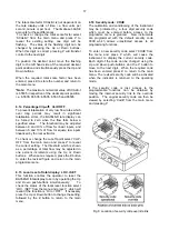
To replace the display assembly remove the
terminal cover by unscrewing the two 'A' screws
which will reveal two concealed 'D' screws.
Unscrew all four 'D' screws and carefully lift off the
front of the instrument as shown in Fig 4.  The
instrument assembly is secured by four Pozi
headed screws which should be removed.  If the
instrument is fitted with a backlight or alarms the
fly-leads connecting the accessory boards to the
terminals should be un-plugged.  The replacement
display assembly may then be installed and the
enclosure reassembled.

If after replacement of the display assembly the
instrument still does not function, it is likely that the
fault is within the protection components on the
terminal assembly.   Terminal assemblies may be
exchanged on-site providing the replacement
includes terminals for any accessories fitted to the
display assembly  i.e. terminals for backlight and
alarms.

We recommend that faulty instruments and
instrument assemblies are returned to BEKA
associates or to our local agent for repair.

8.4 Routine maintenance

The mechanical condition of the instrument and
electrical calibration should be regularly checked.
The interval between inspections depends upon
environmental conditions.  We recommend that
initially instrument calibration should be checked
annually.

8.5  Guarantee

Indicators which fail within the guarantee period
should be returned to BEKA associates or our local
agent.  It is helpful if a brief description of the fault
symptoms is provided.

8.6  Customer comments

BEKA associates is always pleased to receive
comments from customers about our products and
services.  All communications are acknowledged
and whenever possible, suggestions are
implemented.

Содержание BA354ND

Страница 1: ...Issue 3 11th November 2009 BA354ND Type n certified 4 20mA loop powered field mounting rate totaliser issue 3...

Страница 2: ...e P push button 6 13 Total scale factor 6 14 Percentage clip off 6 15 Local reset of total display 6 16 Security code 6 17 Over and under range 7 Calibration Examples 7 1 Using an external current sou...

Страница 3: ...oped across R1 which is proportional to the 4 20mA input current provides the input signal for the analogue to digital converter Each time a 4 20mA current is applied to the instrument initialisation...

Страница 4: ...sc in the lower left hand corner indicator of the display rotates when the input current exceeds 4mA 3 TYPE n CERTIFICATION 3 1 Certificate of Conformity ITS Testing and Certification Ltd Formerly ERA...

Страница 5: ...mmon industrial gases 3 6 Certification Label Information The ATEX certification label is fitted in a recess on the top outer surface of the enclosure The year of manufacture and instrument serial num...

Страница 6: ...gn requirements listed in section 4 1 If suitably certified the flowmeter may also be located in Zone 2 as shown in Fig 3B Both examples show an external reset switch Alternatively the BA354ND may be...

Страница 7: ...safe area To prevent circulating currents cable screens should only be earthed at one point in the safe area The BA354ND enclosure is supplied with a bonding plate to ensure electrical continuity bet...

Страница 8: ...8 Fig 5 Dimensions and terminal connections...

Страница 9: ...s displayed on the five digit display Using the instrument s CAL or SEt functions this display may be calibrated to show the flow rate in engineering units Both the zero display at 4mA and the span di...

Страница 10: ...cimal point clip off to adjust value Press or between 0 and 10 or and pressing Define Security Enter by Code to move to next digit Local reset or Fig 7B Programme Structure CLr Gtot E E E E E E E E P...

Страница 11: ...arly set the required full scale display accurate 20mA input current scale display using an Similarly set the required full to move to next digit pressing or and set required zero display by With accu...

Страница 12: ...l new BA354ND rate totalisers are supplied calibrated as requested at the time of ordering If calibration information is not supplied the BA354ND will be set to display a rate of 0 00 with 4mA input a...

Страница 13: ...n and 4 20 to display current See section 6 12 Display Description of function SCALE T Total Scale Factor Defines the arithmetic relationship between the rate and total displays May be adjusted betwee...

Страница 14: ...ned press E to return to the main menu If the application requires flow rate to be the primary display i e shown on the large display the d P function enables the rate and total displays to be interch...

Страница 15: ...ing the Up and Down buttons and the P button to move to the next digit enter the password SurE Pressing E will then give access to the sub menu Note S is entered as 5 6 9 1 AC rejection FrE WARNING If...

Страница 16: ...lay rate display divided by Per second tb 1 1 Per minute tb 60 60 Per hour tb 3600 3600 Select the required divisor and press E to return to the main menu 6 12 Function of the P push button C P This p...

Страница 17: ...e of total flow may be adjusted in one percent increments using the Up or Down buttons When set as required press the E button to enter the revised figure and return to the main programme menu 6 15 Lo...

Страница 18: ...ing a traceable 4 20mA calibrator Section 7 2 contains an example of calibration using the instruments internal 4 and 20mA references which although not traceable are adequate for many industrial appl...

Страница 19: ...significant digit of the total display and following decimal point are flashing i e a resolution of 0 1 Press P to move control to the rate display Using the Up or Down push button move the flashing d...

Страница 20: ...12 Reset the grand total to zero To reset the grand total to zero select CLr Gtot from the main menu and press P which will cause the instrument to display Clr no Toggle this to CLr YES using the Up o...

Страница 21: ...by simultaneously pressing P and E Assuming a security code has not already been entered the instrument will respond by displaying root which is the first function in the main menu Steps Perform as de...

Страница 22: ...8 8 2 Fault finding after commissioning ENSURE PLANT SAFETY BEFORE STARTING MAINTENANCE Live maintenance should only be performed when there is no risk of a flammable atmosphere being present and dus...

Страница 23: ...accessory boards to the terminals should be un plugged The replacement display assembly may then be installed and the enclosure reassembled If after replacement of the display assembly the instrument...

Страница 24: ...programmed as high or low rate or total alarms with normally open or normally closed outputs Fig 9 illustrates the conditions available for a rate alarm and shows which are fail safe i e output is in...

Страница 25: ...he SCALE t functions and each alarm may be programmed as a rate or a total alarm For simplicity Fig 12 only shows the programmable functions on the rate option of alarm AL1 Alarm 2 and the total optio...

Страница 26: ...s setpoint Sub menu which enables direct access to the alarm setpoints from the operating mode and defines a separate security code See section 9 2 12 9 2 4 Alarm enable EnbL This function allows the...

Страница 27: ...to reveal the current setting The function can be changed by pressing the Up or Down button followed by the E button to return to the alarm menu 9 2 9 Hysteresis HStr Hysteresis is only available on r...

Страница 28: ...de press E to return to the EnbL prompt followed by the Up or Down button to select the access code prompt AcCd Pressing P will reveal the current security code Each digit of the code may be changed b...

Страница 29: ...14 providing the supply voltage is below 30V the backlight safety components will ensure that the input current is less than 100mA Fig 14 Backlight powered by Zener barrier Reducing the supply voltag...

Страница 30: ...commissioning 8 1 after commissioning 8 2 Flow indicator 2 2 Flow transmitter loops 4 1 Gas groups 3 5 Grand total 2 1 clear 6 3 6 10 Guarantee 8 5 HI LO 9 2 3 9 2 7 HStr 9 2 3 9 2 9 Input 4 20mA 3 3...

Отзывы: