18
9.2.2 Type nL certification
Each of the two alarm is a galvanically isolated
single pole solid state switch which has been
certified as a separate Ex nL Group II, Category
3G circuit.
The input safety parameters for each alarm are:
Ui
30V dc
Ii
100mA
Pi
0.2W
This allows each alarm output to switch any dc
circuit providing that in normal operation the
maximum supply voltage is not greater than 30V,
and the current is not greater than 100mA. Pi will
automatically be limited to less than 0.2W by the
safety components within the indicator.
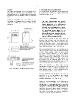
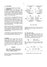
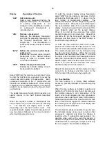
Fig 10 shows an typical application in which a
BA324ND is displaying the output from a 2-wire
transmitter in Zone 2. Alarm 1 is controlling a
solenoid valve and alarm 2 a sounder in the safe
area.
Fig 10 Typical alarm application
9.2.3 Programming and adjustment
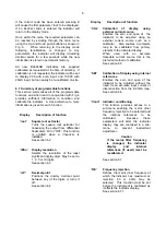
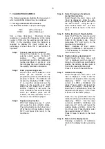
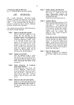
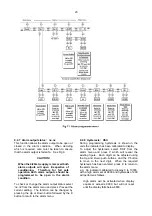
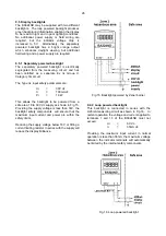
When an alarm card is added to a BA324ND the
main programme menu is extended as shown in
Fig 11. The additional functions appear between
'Cond' and 'C--P' in the main menu. For simplicity
Fig 11 only shows the additional functions
available on alarm 1, but alarm 2 has identical
facilities.
The following table summarises each of the alarm
programme functions and includes a cross
reference to more detailed information. Again
only the functions on alarm 1 are listed, but alarm
2 has identical facilities.
Summary of programmable alarm functions
Display
Description of function
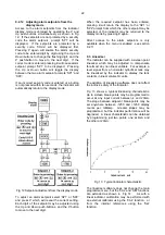
'EnbL'
Alarm enable
Enables or disables the alarm
function without changing the alarm
parameters.
See section 9.2.4
'SP1'
Alarm setpoint 1
Adjusts the alarm setpoint. The alarm
is activated when the indicator display
equals the setpoint.
See section 9.2.5
'HI.LO'
Alarm function
Defines whether the alarm has a high
or low function.
See section 9.2.6
'no.nc'
Normally open or normally closed
output
Determines whether the single pole
alarm output is open or closed in the
alarm condition.
See section 9.2.7
'HStr'
Hysteresis
Adjusts the alarm hysteresis.
See section 9.2.8
'dELA'
Alarm delay time
Adjusts the delay between the display
equalling the setpoint and the alarm
output being activated.
See section 9.2.9
'SIL'
Alarm silence time
Defines the time that the alarm output
remains in the non-alarm condition
following acceptance of an alarm.
See section 9.2.10
'AcSP'
Access setpoint
Sub-menu which enables direct
access to the alarm setpoints from the
indicator display mode, and defines a
separate security code.
See section 9.2.11


