background image

BEIJING HUAHUAN ELECTRONICS Co., LTD. 


H9MO-1641S User Guide V2.2


- P. 

21

 - 


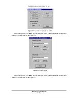
From the window of the OLT-B pop up, that is used for status display and defining the ‘Alarm 

Indicator’; ‘Loopback’; ‘J0 Byte Setup’; ‘J1 Byte Setup’; and ‘Self Healing Mode’. ‘Loopback’ is used for 
the OLT-B interface only. 

For the setup and display of ‘J0 Byte Setup’; ‘J1 Byte Setup’; and ‘Self Healing Mode’ it is the 

exactly the same as shown on OLT-A interface setting.   

5.3 OLT-C 

Interface 

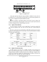
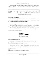
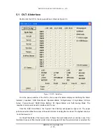
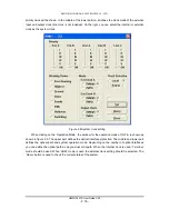
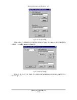
Double click the OLT-B, the pop-up window is shown as figure 5.14. 


Figure 5.14 OLT-C interface 

From the pop-up window of the OLT-C, that is used for status display and defining the ‘Alarm 

Indicator’; ‘Loopback’; ‘J0 Byte Setup’; ‘J1 Byte Setup’; and ‘Self Healing Mode’. ‘Loopback’ is used for 
interface OLT-C only. 

‘Operation Mode’; ‘J0 Byte Setup’; ‘J1 Byte Setup’; and ‘Self Healing Mode’ is the exactly the same 

as shown on the OLT-B interface setting.   

5.4 Ethernet 

Interface 

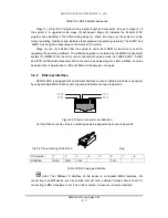
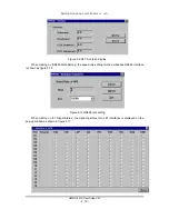
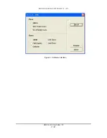
Double click the Ethernet interface on the rightmost side of the H9MO-1641S icon, the pop-up 

window is shown as figure 5.16. The window shows the alarm status, module reset and clear routing 
table. 

Содержание H9MO-1641S

Страница 1: ...H9MO 1641S STM 1 MSTP User Guide Beijing Huahuan Electronics Co Ltd 2005 2 ...

Страница 2: ...es that may appear in the document Copyright 2005 by Beijing Huahuan Electronics Co Ltd All rights reserved No part of this publication may be reproduced or distributed in any form or by any means without prior written permission of Huahuan Product Model H9MO 1641S Product Name STM 1 MSTP Manual Version 2 2 English Last Update 2005 2 BEIJING HUAHUAN ELECTRONICS Co LTD Address No 26 Shangdi 6th Str...

Страница 3: ...N 4 3 1 EQUIPMENT CONFIGURATION 4 3 2 FRONT PANEL 6 3 2 1 INDICATORS 6 3 2 2 ETHERNET INTERFACE 7 3 2 3 OPTICAL INTERFACE 8 3 2 4 SERVICE PHONE INTERFACE 8 3 2 5 LCD DISPLAY 8 3 3 REAR PANEL 10 3 3 1 E1 INTERFACES ADAPTOR BOARD 10 3 3 2 SYSTEM CLOCK INTERFACE 11 3 3 3 MONITOR PORT SV INTERFACE 11 3 3 4 DATA PORT INTERFACE 12 3 3 5 ALARM OUTPUT CONNECTOR 12 3 3 6 GROUNDING CONNECTOR 12 3 3 7 POWER ...

Страница 4: ...LT C INTERFACE 21 5 4 ETHERNET INTERFACE 21 6 SYSTEM SPECIFICATIONS 23 6 1 STANDARD COMPLIANT 23 6 2 BASIC CHARACTERISTIC 23 6 3 OPTICAL INTERFACE SPECIFICATIONS 23 6 4 2MBPS INTERFACE ELECTRICAL CHARACTERISTICS 23 6 5 ETHERNET DATA INTERFACE CHARACTERISTICS 24 6 6 EXTERNAL SYNCHRONIZATION 24 6 7 MANAGEMENT INTERFACE 24 6 8 SYSTEM POWER SUPPLY 24 6 9 WORKING ENVIRONMENT 24 6 10 DIMENSIONS 24 6 11 ...

Страница 5: ...i node networks with complicated topological structures Special technical provisions have been adopted in the equipment to suppress LF jittering in the E1 channel with parameters that exceed the requirements in the latest ITU T G 823 recommendation H9MO 1641S integrates the data service access exchange and transmission and has greatly raised the transmission efficiency by means of the statistical ...

Страница 6: ... H9MO 1641S multiplexers A B Main Node A B B B A A C Figure 2 1 Ring network All devices in figure 2 1 are of the relay type The A and B marked on both sides of devices represents respectively the Optical Port A and Optical Port B of the device irrespective of actual transmission direction The connection lines between the devices are optical cables and the arrows indicate signal directions Please ...

Страница 7: ...re 2 2 can be formed using the H9MO 1641S multiplexer B A A A Figure 2 2 Chain network In figure 2 2 both the home and terminal equipment are terminal equipment and the remaining multiplexer is of relay type A and B represents Optical port A and Optical port B of the device irrespective of the actual transmission direction Two terminal devices can also form a point to point connection Please note ...

Страница 8: ...tiplexer It supports a number of optical terminal boards and sub network protection of channels The multiplexer can be formed into various network topological structures to suit the application or network topology requirements The H9MO 155 and H9MO 1641S equipment in the network shown in Figure 2 4 are all of relay type except the terminal station device The east and west marked on both sides of e...

Страница 9: ...ay device is that the terminal device is only equipped with one OLT board while a relay device needs two By adding one OLT board a terminal device can be turned into a relay device This network structure is suitable for phased construction and extension of networks The H9MO 1641S supports Ethernet by adding the optional ETH board The AC or DC power supply is customer defined at order Board positio...

Страница 10: ...ight of the front panel for a fully equipped H9MO 1641S LED Color Description PWR Green Lit Power normal ALMP Red Lit Major alarm ALMD Yellow Lit Minor alarm SYS Green Flashing System function normal FDX Green Flashing Data transmit and receive Link Act Green Lit Link active Table 3 1 LED description When the H9MO 1641S is in boot up mode or software upgrade mode the indicators ALMP ALMD and SYS h...

Страница 11: ...in upload mode all 3 LEDs ALMP ALMD and SYS will flash simultaneously When the code is downloading all 3 LEDs will flash once the download has completed the 3 LEDs will flash simultaneously once again 3 2 2 Ethernet Interface H9MO 1641S is equipped with an Ethernet interface connector Ethernet module is an option by using standard MDI II RJ45 socket Signal pin definition is shown in figure3 3 Figu...

Страница 12: ...aser may damage the eye permanently 3 2 4 Service Phone Interface The H9MO 1641S provides an RJ11 connector for the service phone line order wire via the E1 overhead bit in the STM 1 frame structure The order wire phone provides service contact between the nodes on the network it also functions as an input panel for the control of the LCD display details of which are in the next section The order ...

Страница 13: ...Menu 1 LocalInfo 2 StateInfo 3 AlarmInfo StateInfo 1 ClkInfo 2 FrameInfo 3 OltMode 4 OltPrInfo AlarmInfo 1 OltAlarm 2 ClkAlarm 3 E1RDI 4 E1AIS 5 E1LOS 6 E1LOP 0 15 0 15 0 15 4 MaskCtrl 1 0 1 2 3 4 5 6 MaskCtrl 1 SetMask 2 ClrMask 4 0 2 0 Huahuan H9MO 1641S On Hook Off Hook IP IP Addr 485BR 485 Baud Rate Tel Phone number VerS Software Version LocalInfo VerE Ethernet Version Figure 3 5 Command flowc...

Страница 14: ... clock A LBBad Bad line clock B LCBad Bad line clock C RDI Remote failure detected indication LOP TU 12 pointer loss AIS Alarm indication for E1 port all 1 received LOS Loss of signal on E1 port VerS Software version VerE Ethernet module version 485BR RS485 port baud rate Table 3 4 Acronym of LCD display 3 3 Rear Panel The rear panel of the H9MO 1641S is shown in figure 3 6 1 0 ON OFF 220V 50Hz A ...

Страница 15: ...ctors labeled as CLK1 and CLK2 and one output clock connector labeled as OUT The input or output clock uses the 2048 KHz or 2048 Kbit s synchronous clock and the impedance is 75 ohm coaxial or 120 ohm wire wrap The clock mode and impedance is defined on the main circuit board as below Terminal Impedance Jumper Position 75 ohm Up CLK1 120 ohm CNM 10 Down 75 ohm Up CLK2 120 ohm CNM 9 Down Table 3 5 ...

Страница 16: ...pin alarm connector is used for external audible bell or visible light alarms These conditions are defined by inputting the required outputs into the management system When using the rack alarm controller for power and alarm monitoring plug in the accessory cable which comes with the controller as shown in figure 3 8 The alarm controller supports both audible and visible alarms simultaneously Figu...

Страница 17: ...ing of the H9MO 1641S multiplexer you should take note of the following recommendations 1 Ensure that you have all the corresponding parts and optional modules that are required for your application 2 Ensure that you connect all cabling in accordance with the manufactures instructions 3 Do not attempt to change any change internal settings or tunable components on the mother board Any attempt to d...

Страница 18: ... the unit by using the setaddr command Refer to the H7 GMSW management software guide to add a new device of the system the equipment icon will be displayed as shown in figure 5 1 The three optical buttons from left to right represents the OLT C C OLT B B and OLT A A interface Note that the OLT B and OLT C interfaces are optional and may not have function depending upon the actual system configura...

Страница 19: ...te Setup Version Query RS485 Rate Setting E1 Signal Status and Self Healing Mode The Loopback command is used for interface OLT A only Click the SDH Clock Mode the System Clock Setting will appear as figure 5 4 The upper portion is used to define the priority of the external clock including the line clock The highest priority is I and the lowest is V On the left hand side of the lower portion it s...

Страница 20: ... clicking on the Operation Mode the window for the operation mode of OLT A is shown as shown in figure 5 5 The upper part defines the optical interface protection The middle and lower part defines the optical path and system operation mode Depending on the number of optical interfaces you can define the optical path as single dual or tri path When the internal clock is used Terminal mode should be...

Страница 21: ...LT A When clicking on J0 Byte Setup and after clicking on Query the pop up window of the J0 byte of the OLT A interface as shown in figure 5 6 Figure 5 6 J0 byte setting When clicking on J1 Byte Setup and after clicking on Query the pop up window of the J1 byte of the OLT A interface as shown in figure 5 7 ...

Страница 22: ...yte setting When clicking on J2 Byte Setup and after clicking on Query the pop up window of the J2 byte of the OLT A interface as shown in figure 5 8 Figure 5 8 J2 byte setting When clicking on Version Query the software and hardware version number of the OLT A is shown in figure 5 9 ...

Страница 23: ...n display When clicking on RS485 Rate Setting the speed rate setting for the embedded RS485 interface is shown as figure 5 10 Figure 5 10 RS485 rate setting When clicking on E1 Signal Status the signaling status for all E1 interfaces is displayed on the pop up window as shown in figure 5 11 ...

Страница 24: ...channels signal status When clicking on Self Healing Mode the self healing mode of the OLT A pop up is shown in figure 5 12 Figure 5 12 Self healing mode of OLT A 5 2 OLT B Interface When double clicking the OLT B the pop up window is shown in figure 5 13 Figure 5 13 OLT B interface ...

Страница 25: ...uble click the OLT B the pop up window is shown as figure 5 14 Figure 5 14 OLT C interface From the pop up window of the OLT C that is used for status display and defining the Alarm Indicator Loopback J0 Byte Setup J1 Byte Setup and Self Healing Mode Loopback is used for interface OLT C only Operation Mode J0 Byte Setup J1 Byte Setup and Self Healing Mode is the exactly the same as shown on the OL...

Страница 26: ...BEIJING HUAHUAN ELECTRONICS Co LTD H9MO 1641S User Guide V2 2 P 22 Figure 5 15 Ethernet interface ...

Страница 27: ...er ADM Network topology Dual ring mesh chain and branch network Group route capacity Max 3 x 155 520Kbit s STM 1 optic interface Branch capacity Max 16 x 2 048Kbit s digital signal E1 and 1 x 100Mbps Ethernet 6 3 Optical interface specifications Transmission code rate 155 520kbit s STM 1 G 957 G 707 framing Line code type scramble code NRZ Connector FC socket Optical sending average power S1 1 1 3...

Страница 28: ... 0 2 3 75Ω Wire wrap terminal 120Ω 6 7 Management interface Dedicated interface 4 wire RS485 TABS protocol 15 pin type D socket Data bit 8 stop bit 1 odd parity 1 200 38 400 bps selectable F interface RS232 9 600 bps 8 data bit 1 stop bit none parity 6 8 System power supply Input voltage AC 220V permissible variation range 170V 260V DC 48V permissible variation range 40V 65V Power consumption 50W ...

Отзывы: