Behringer UL2000M Скачать руководство пользователя страница 14

14

ULTRALINK UL2000M

7.

After a second blink pause, an additional blink code is given as a confirmation:

A successfully stored frequency is signaled with 2 slow blinks. The transmitter leaves the
programming mode.
If the LED blinks quickly 5 times, the frequency was not stored. In this case, start anew with step 2.

If no entry is made for more than 5 seconds (either on the selection switch or by pressing the
POWER button), the LED blinks quickly 5 times, and the programming mode is aborted.

8.

Disengage the MUTE switch.

A user-assigned frequency is automatically stored in the user preset (Preset 1)!

3.2.4 Preset

The ULM2000 lets you work with 4 presets,  each with 8 channels.

Factory presets (Presets 2, 3 and 4)
In the ULM2000, there are 3 factory presets (each with 8 interference-free channels). That means that all 8
channels of one preset can run simultaneously with 8 different transmitters and receivers without causing
interference to one another.

The channels in the 3 factory presets are all assigned to different frequencies. This way, you can always
select a frequency range that assures the best signal transmission.

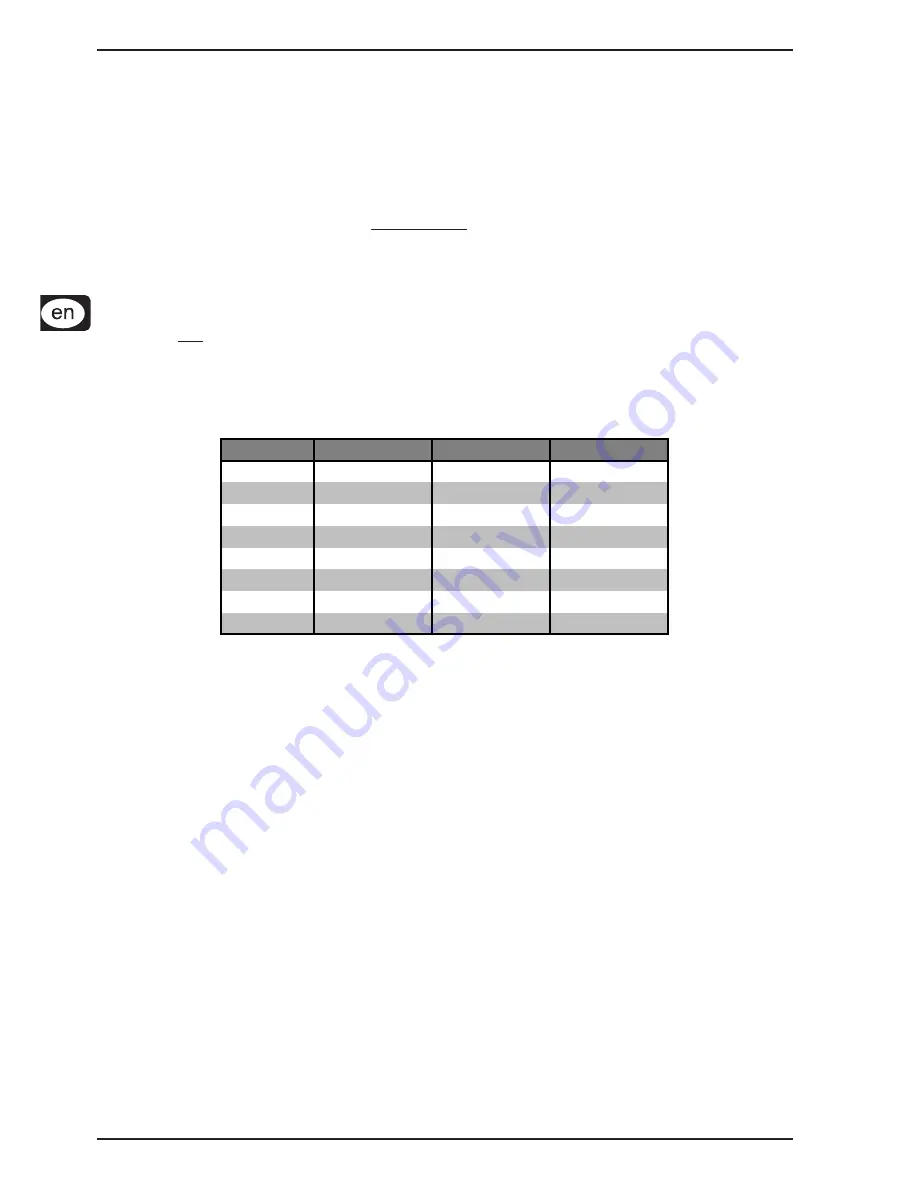
The following table shows which frequencies are stored in the factory presets.

CHANNEL

PRESET 2

PRESET 3

PRESET 4

1

798,700 MHz

798,400 MHz

798,100 MHz

2

799,950 MHz

798,950 MHz

798,650 MHz

3

800,650 MHz

799,800 MHz

799,500 MHz

4

801,050 MHz

801,450 MHz

801,150 MHz

5

802,850 MHz

803,250 MHz

802,950 MHz

6

804,500 MHz

803,650 MHz

803,350 MHz

7

805,350 MHz

804,350 MHz

804,050 MHz

8

805,900 MHz

805,600 MHz

805,300 MHz

Tolerance 0.005%

Table 3.1: Factory preset frequencies (presets 2,3 and 4)

User preset (Preset 1)
Preset 1 is meant for the user. Frequencies of your own choice can be stored in the 8 storage slots of this
preset.

If you have not stored any of your own frequencies, the frequencies stored in the user preset (Preset 1) are
identical to the frequencies stored in Preset 3.

Loading a preset
1.

Engage MUTE. The transmitter can now be switched into the programming mode.

2.

Turn the selection switch to 0 and confirm your selection by keeping the POWER button pressed for 2
seconds. As a confirmation, the LED blinks slowly once and then once again with medium tempo. The
transmitter is now in the programming mode and waits for you to enter a one-digit number.

3.

Select the desired preset number on the selection switch, e.g. 3 (possible choices: 1 - 4). If a valid
selection is made, the LED blinks once quickly to confirm your selection. This way, you can be sure that
a correct value is entered (in regard to the selection of presets, Mic Gain and Auto Mute) even before
confirming your selection.

Selecting 5 or 6 changes the Mic Gain setting (ch. 3.2.5). Selecting 7 or 8 changes the Auto
Mute settings (ch. 3.2.6). Values 9 and 0 are invalid.

4.

Confirm your selection by briefly pressing the POWER button.

5.

If the selection you made is valid, the LED blinks quickly once again. An invalid selection is indicated
with 5 quick blinks, and the unit is immediately no longer in the programming mode. In this case, start
anew with step 2.
After a brief break, a second blink code is given: The LED blinks according to the value selected (for
example, in this case 3 times) with medium tempo.

3. ULM2000 MICROPHONE

Содержание UL2000M

Страница 1: ...User s manual A50 13413 00005 ULTRALINK UL2000M ...

Страница 2: ...ere they exit from the apparatus 10 Only use attachments accessories specified by the manufacturer 11 Use only with the cart stand tripod bracket or table specified by the manufacturer or sold with the apparatus When a cart is used use caution when moving the cart apparatus combination to avoid injury from tipping over 12 Unplug this apparatus during lightning storms or when unused for long period...

Страница 3: ...ontrol elements 12 3 2 Hand held transmitter operation 12 3 2 1 Turning the microphone on 12 3 2 2 Channel setting 12 3 2 3 Setting your own frequency 13 3 2 4 Preset 14 3 2 5 Mic Gain 15 3 2 6 Auto Mute 15 3 2 7 Turning the microphone off 16 3 3 Status query 16 3 3 1 Battery condition and transmission channel 16 3 3 2 Transmission frequency 17 3 3 3 Preset 17 3 3 4 Mic Gain 17 3 3 5 Auto Mute 17 ...

Страница 4: ...ne either by observing the transmission channel in the display or by comparing the transmission frequency In addition the ULTRALINK equipment from BEHRINGER leaves you the option to color code your gear for easy identification Beyond that both units feature other useful functions such as Scan and Auto Mute This way no wishes are left open during practice or in live situations The following instruc...

Страница 5: ...polarity Labels for battery orientation are found in each battery holder of the compartment 3 Keep the microphone in the usual upright position and begin by placing the bottom battery 4 Remove the base plate in order to connect the battery to the contacts Re insert the plate to ensure the battery fits securely 5 To place the second battery turn it upside down Insert the battery with the bottom end...

Страница 6: ...s with unbalanced connections the maximum signal level is 6 5 dBu We would like to point out that high volume levels may cause distortion and high signal levels in other equipment to which your ULR2000 is connected e g mixing console or headphones High volume levels may damage your hearing and or your headphones speakers Please turn the VOLUME control all the way to the left very low output signal...

Страница 7: ...o a distortion gauge on a mixer or an amplifier the 8 level AF indicator shows how loud the demodulated audio signal Audio Frequency is If the signal has no amplitude or if the amplitude is low no bars are shown The maximum undistorted AF level is received when 7 bars and not 8 light up Only when the audio signal is overdriving or when no RF signal can be received the receiver creates too much noi...

Страница 8: ... different options to individually configure the receiver By using the UP and DOWN buttons you can select various menu items e g TUNE SCAN Pressing the SET button once gets you into the respective submenu e g submenu TUNE By pressing the UP and DOWN buttons you can select different settings in the submenu Pressing the SET button again confirms your selection If menu is selected and you make no par...

Страница 9: ...save your settings Depending on the basic settings the ULR2000 asks you to enter a channel color BLUE RED or a channel number CHAN1 CHAN2 7 A storage location can be selected by pressing the UP or DOWN buttons 8 Press the SET button again to store your frequency at the location you selected The procedure is now over and the basic settings are shown in the display again A scan can also be halted ma...

Страница 10: ...at means that the channel you selected last is shown you can change this channel immediately without going to menu by using the UP and DOWN buttons There are 3 different ways to show the selected channel in the display You can decide for yourself which representation is the most appropriate for your applications The exact channel carrier frequency is shown FREQU The channel number is shown in the ...

Страница 11: ... 798 700 MHz 798 400 MHz 798 100 MHz 2 799 950 MHz 798 950 MHz 798 650 MHz 3 800 650 MHz 799 800 MHz 799 500 MHz 4 801 050 MHz 801 450 MHz 801 150 MHz 5 802 850 MHz 803 250 MHz 802 950 MHz 6 804 500 MHz 803 650 MHz 803 350 MHz 7 805 350 MHz 804 350 MHz 804 050 MHz 8 805 900 MHz 805 600 MHz 805 300 MHz Tolerance 0 005 Table 2 1 Factory preset frequencies presets 2 3 and 4 User preset Preset 1 Prese...

Страница 12: ...d to programming mode by selecting the digits 9 or 0 or you can get a readout of a specific unit setting SELECTION SWITCH Using a screwdriver you can select different values on the SELECTION SWITCH For example you can select a channel number and the frequency The SERIAL NUMBER is located on the transmitter battery compartment To get to the serial number please open the battery compartment see ch 1...

Страница 13: ... one after another in the following fashion Select the desired value on the selection switch for example 4 If a valid value is selected the LED blinks quickly once as a confirmation This way you can be sure that a correct value is entered in regard to the frequency range and divisibility by 25 kHz even before confirming your selection Confirm your selection by briefly pressing the POWER button If ...

Страница 14: ...05 900 MHz 805 600 MHz 805 300 MHz Tolerance 0 005 Table 3 1 Factory preset frequencies presets 2 3 and 4 User preset Preset 1 Preset 1 is meant for the user Frequencies of your own choice can be stored in the 8 storage slots of this preset If you have not stored any of your own frequencies the frequencies stored in the user preset Preset 1 are identical to the frequencies stored in Preset 3 Loadi...

Страница 15: ... 0 are invalid 4 Confirm your selection by briefly pressing the POWER button 5 If the selection you made is valid the LED blinks quickly once again An invalid selection is indicated with 5 quick blinks and the unit is immediately no longer in the programming mode In this case start anew with step 2 After a brief break a second blink code is given The LED blinks according to the value selected for ...

Страница 16: ...links once at middle tempo Auto Mute engaged the LED blinks twice at middle tempo If no entry is made for more than 5 seconds either on the selection switch or by pressing the POWER button the LED blinks quickly 5 times and the programming mode is aborted 6 After a second brief blink break an additional blink code is given as a confirmation Two slow blinks signal that the Auto Mute setting was cha...

Страница 17: ... 3 The LED indicates the Mic Gain status with the corresponding number of medium tempo blinks Low Gain The LED blinks once with medium tempo High Gain The LED blinks twice with medium tempo 3 3 5 Auto Mute 1 Make sure that the microphone is not set to mute MUTE switch is set to OFF 2 Turn the selection switch to 7 or 8 and confirm your selection by briefly pressing the POWER button 3 The LED indic...

Страница 18: ...iators metal racks reinforced concrete walls and similar The devices should always be at a height of at least 1 m 3 ft off the ground To assure good reception in many different positions we advise against having the antennae point at a 90 degree angle Instead antennae should be arranged at an angle of no more than 40 in respect to one another To assure interference free reception ideally there sho...

Страница 19: ...re good reception if possible install the ULR2000 as high in a rack as possible so that the antennae protrude above the upper edge of the rack The ULR2000 requires one height unit 1 HE for installation in a 19 inch rack Please assure that there are additional 10 cm 4 inches of free space in the back for connecting cables For installation in a rack use M6 machine screws and nuts Be sure that there ...

Страница 20: ... equipment to the balanced connectors Fig 5 2 XLR connections Fig 5 3 1 4 TS connector Fig 5 4 1 4 TRS connector Unlike other microphones the ULM2000 hand held transmitter can not be connected using a cable It connects to the ULR2000 receiver wirelessly Cables are only used to pass the signal from the receiver farther down the signal path 5 INSTALLATION ...

Страница 21: ...f SNR Antenna inputs 2 BNC connectors Antenna input impedance 50 Ω Range 100 m nominal coupled with the ULM2000 transmitter under optimal environmental conditions AF characteristics coupled to ULM2000 Noise reduction high performance IRC compander system Pre Deemphase AF frequency response 30 19000 Hz 3dB THD at nom deviation and 1kHzNF 0 4 SNR at peak deviation 105 dB A Noise limiter switching th...

Страница 22: ...every effort to ensure the highest standards of quality Necessary modifications are carried out without notice Thus the specifications and design of the device may differ from the information given in this manual Technicalspecificationsandappearancesubjecttochangewithoutnotice Theinformationcontainedhereiniscorrectatthetimeofprinting The names of companies institutions or publications pictured or ...

Страница 23: ...nd on the user is encouraged to try to correct the interference by one or more of the following measures Reorient or relocate the receiving antenna Increase the separation between the equipment and receiver Connect the equipment into an outlet on a circuit different from that to which the receiver is connected Consult the dealer or an experienced radio TV technician for help Operation is subject t...

Страница 24: ...24 ULTRALINK UL2000M MICROPHONE QUICK START GUIDE MICROPHONE QUICK START GUIDE ...

Отзывы: