


8
FEEDBACK DESTROYER PRO FBQ2496 User Manual
9
FEEDBACK DESTROYER PRO FBQ2496 User Manual
4.2 Setting up parametric fi lters
Some or even all 40 fi lters on your FBQ2496 can be deployed as parametric fi lters.
They have to be set up in a targeted fashion, with great precision. The frequency,
bandwidth and gain parameters are available.
Selecting the number of parametric fi lters
1. Keep the PEQ button pressed for a few moments. The LED on the PEQ button
blinks, and the display shows the current number of parametric fi lters (p 0 =
no parametric fi lters deployed, P20 = all fi lters are parametric). Additionally,
the LEDs on the deployed Single-Shot fi lters are lit.
2. You can use the wheel to change the number of parametric fi lters.
The display shows the number of deployed parametric fi lters, and the
corresponding LEDs in the status display (
(8)
) are lit.
3. Pressing the PEQ button again briefl y completes the procedure.
•
•
Now, the only parametric fi lters whose LEDs are still lit are those whose
gain (either positive or negative) does not equal zero.
Setting up frequency, bandwidth, gain
You should implement the following procedure with each individual
parametric fi lter:
1. Briefl y press the PEQ button.
The LED on the PEQ button is lit. The display indicates the number of the
selected fi lter (e.g.
19
).
2. Use the wheel to select the parametric fi lter whose values you wish
to modify.
◊
◊
Any filter may be selected using the wheel! However, the parameters of
the Single-Shot and automatic filters can only be displays and can not
be modified!
3. After you press the FREQUENCY button, use the wheel to set the fi lter mid
frequency (the LED on the button blinks).
You can get a precise readout of the set mid frequency by observing the
display and the status of the Hz/kHz LED next to it.
To modify exactly the frequency band you have in mind, you can shift the
fi lter
’
s bandwidth.
4. Briefl y press the BANDWIDTH button.
5. Turning the wheel changes the fi lter
’
s bandwidth. The 1/60 LED lights up if
a value lower than 0.1 is set (
1
x 1/60,
2
x 1/60 ...
5
x 1/60). In case of larger
bandwidths, the value is shown directly in the display (
0.1
,
0.2
...
1.0
,
1.1
...
10.0
).
A parametric fi lter becomes engaged only after an increase/decrease of the set
frequency is entered:
6. Briefl y press the GAIN button. The LED on the button is lit. At the same time,
the dB LED under the 3-digit display is also lit.
7. The gain can be adjusted using the wheel. The available values range from
15 dB to - 36 dB (can be changed in 0.5-dB increments in the +15 dB to
-15 dB range; in 1-dB increments in the -16 to -36 dB range). The value is
shown in the display.
◊
◊
The FBQ2496 has a 3-digit display. Positive values are easily represented
(
14, 14.5, 15
). For negative values, complete representation would
require 4 digits. However, because the display only shows 3 digits,
the position after the decimal point is omitted and replaced by a
dot to the right of the first two digits
(
-15
,
-14.
(5)
,
-14
,
-13.
(5))
,
which stands for the missing decimal value.
8. Press the PEQ button briefl y again to complete the procedure.
◊
◊
The status display only shows the filters whose gain does not equal to
zero (either positive or negative).
4.3 Setting up automatic fi lters
The number of automatic fi lters can not be separately set. It results from the
number of fi xed and parametric fi lters (fi g. 4.2).
◊
◊
To lower the number of automatic filters, increase the number of
Single-Shot and/or parametric filters.
The automatic fi lters automatically spring into action on a per-need basis during
a performance or a recording session. Of course, having the FBQ2496 react to
changing situations would be desirable. To allow for this, you need to establish
a setup in which the automatic fi lters are only periodically active, setting
themselves back to zero afterwards in order to be ready for the next instance in
which feedback is occurring.
The so-called “Filter Lifting Time” informs you about how long a fi lter set to
automatic may remain active before its values are reset back to zero. This Filter
Lifting Time can be set on the FBQ2496.
1. Press the FILTER LIFT button. The LED on the button starts to blink.
2. Using the wheel, Filter Lifting Time can either be turned off (
off
) or can be
set to 1 min, 5 min, 10 min, 30 min or 60 min.
3. To exit this menu, press the FILTER LIFT button again. The LED no
longer blinks.
4. If a Filter Lifting Time value has been set (i.e. any value other than
off
!),
the button LED is lit.
◊
◊
If a satisfactory setting for the Single-Shot and automatic filters
has been achieved, you can keep this setting by pressing the FREEZE
button. The display shows: -.
5. Connectivity Options
◊
◊
The FEEDBACK DESTROYER PRO is not intended to be connected directly
to the microphones! If this is unavoidable, then we recommend our
proven BEHRINGER SHARK DSP110 instead, which is equipped with a
dedicated microphone preamplifier.
◊
◊
No amount of fancy gear can undo the mistakes committed when
selecting the locations for microphones! Therefore, when you
set up your mics, use them according to their directivity and
feedback susceptibility.
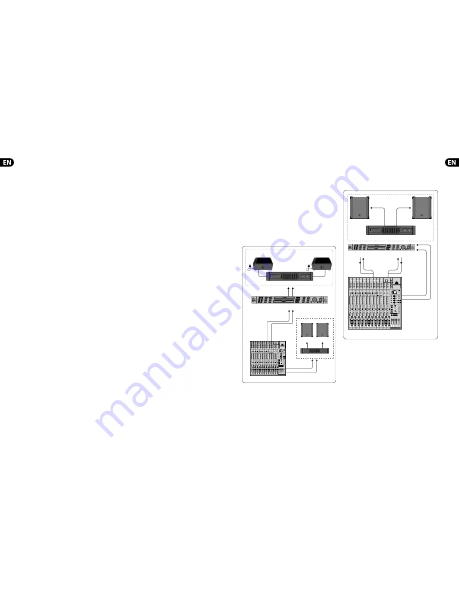
5.1 FBQ2496 in the monitor path
Due to its 2-channel architecture, the FBQ2496 is ideal for use with two monitor
paths. Connect your mixing console
’
s pre-fader aux outputs to the FBQ2496
inputs, as shown in fi g. 5.1. The monitor power amp inputs are then connected to
the FBQ2496 outputs.
Using the FBQ2496 in the monitor path can considerably augment the
volume level.
EURORACK UB2442FX-PRO
EUROLIVE B1220 PRO
FEEDBACK DESTROYER PRO FBQ2496
Pre-Fader
AUX SENDS 1
Pre-Fader
AUX SENDS 2
MAIN
OUTPUTS
OUTPUT
LEFT
INPUT
LEFT
OUTPUT
RIGHT
INPUT
RIGHT
Monitor System
PA System
FLOOR MONITOR F1220A
FLOOR MONITOR F1220A
EUROPOWER EP2000
EUROPOWER EP2000
Fig. 5.1: Using the FBQ2496 in the monitor path
5.2 FBQ2496 in channel insert
Since you want to make sure that deliberately produced feedback signals, such as
“guitar feedback,” are not eliminated, try inserting the FBQ2496 into those
channels that are susceptible to feedback. For example, you could process a vocal
microphone that is prone to producing feedback by connecting the FBQ2496 to
the insert points of the respective channel.
PA System
INPUT
LEFT
EUROLIVE B1220
EUROLIVE B1220
EUROPOWER EP1500
INPUT
RIGHT
OUTPUT
RIGHT
MAIN
OUTPUTS
INSERT
EURORACK UB2442FX-PRO
OUTPUT
LEFT
FEEDBACK DESTROYER PRO FBQ2496
Fig. 5.2: FEEDBACK DESTROYER PRO in channel insert/subgroup insert
◊
◊
When processing a microphone signal with the DSP1124P and a
compressor inserted into the same channel insert point, the FBQ2496
should always be used pre-compressor.
If your mixing console features subgroups with their own inserts, this is perfect
for connecting the FBQ2496! Route all the channels prone to feedback (e.g. all
vocal microphones) to one subgroup. This way, channels that are less prone to
feedback (e.g. line signals, instrument microphones with lower signal levels)
can freely pass through the FBQ2496; only the critical microphone channels are
being modifi ed.
In case your mixing console features no subgroup insert, we recommend
the following: connect the subgroup output to one FBQ2496 input. On the
other hand, the corresponding output is either connected to an unused line
input of a mixer channel or to one of its Aux Return inputs. As long as both
FBQ2496 channels are not coupled, the second FEEDBACK DESTROYER PRO
channel is available to you for a completely diff erent purpose (e.g. use it on a
channel insert).
Содержание FEEDBACK DESTROYER PRO FBQ2496
Страница 9: ...Dedicate Your Life to MUSIC...


