11
4.0 Determination of the Rotary Field
The phase sequence of the three phases present determines the
rotary direction of the motor connected. The correct phase sequence
L1, L2, L3 results in a clockwise rotation.
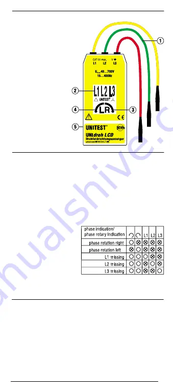
For phase sequence determination connect the three clamps L1,
L2, L3 in any order to the three phase system. LED/LCD-Segment
(3) is illuminated for a clockwise rotary field. If LED/LCD-Segment
(2) is illuminated, exchange
two connections.
Please also refer to table
at the backside of the unit
Correct phase sequence is
displayed even if neutral N
is connected instead of L1,
L2 or L3. Correct phase connection has to be verified by two-
pole voltage test.
5.0 Maintenance
When using the instrument in compliance with the instruction
manual no special maintenance is required.
5.1 Cleaning
If the instrument is dirty after usage, it is advised to clean it by
using a humid cloth and mild household detergents. Never use
acid detergents or dissolvants.
UNI
dreh LCD
/ UNI
dreh EVU
1. Connecting lines with safety
plugs.
2. LCD-Segments for phase
indication L1, L2, L3.
3. LCD-Segments
for clockwise
rotary phase indication.
4. LCD-Segments
for anti-clockwise
rotary phase indication.
5. Brief instructions
on instrument rear.
300


