background image

Chapter 4

Configuration and Status

38

Bedrock SPS.500 User Manual - BRDOC125_007

9/3/21

The SPS.500 must have its IPv4 information configured as described in the 

Bedrock IDE Device Management section above.
To ensure a proper connection to the OPC UA client, the Keep

-

Alive Count 

must be set to no slower than six seconds. Bedrock recommends setting the 

Keep

-

Alive Count to three seconds.

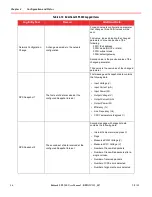
The OPC UA tags that are available for the SPS.500 are listed in Table 4

-

11.

Table 4

-

11   OPC UA Tags for the SPS.500

Tag Name

 Description

Units

Read/Write

Input Voltage

AC input voltage to the SPS

V AC RMS

RO

Input Current

Input current to the SPS

Amps RMS

RO

Input Power

Input power to the SPS

Watts

RO

Enabled

Turns the SPS on or off

RO

Output Voltage

Voltage on the 24 V output of the SPS

Volts DC

RO

Output Current 

Output current on the main DC output

Amps

RO

Output Power

Output power from the SPS

Watts

RO

Efficiency

Calculated efficiency of the SPS

Percent

RO

Line Frequency

Measured frequency of the AC input

Hertz

RO

CPU Temperature

Measured temperature of the CPU

Degrees 

Celsius

RO

Internal Temperature

Measured temperature of the switching converter

Degrees 

Celsius

RO

Output Voltage Setting

Sets voltage on the 24 V output of the SPS 

Volts

RO

Faults

A non-zero value indicates a fault on the PFC controller of 

the SPS. This is a 16-bit value that indicates faults as 

follows:

     Bit   6:     1 = update fault

     Bit   5:     1 = PWM fault

     Bit   4:     1 = input frequency fault

     Bit   3:     1 = output overcurrent fault

     Bit   2:     1 = input undervoltage fault

     Bit   1:     1 = AC_OK fault

     Bit   0:     1 = P_Good fault

RO

Содержание SPS.500

Страница 1: ...Revision 7 September 2021 Bedrock OSA SPS 500 User Manual ...

Страница 2: ...th any installation Bedrock Automation cannot assume responsibility or liability for actual use based on the examples diagrams or information included in this manual Nothing in this disclaimer excludes or limits any warranty that is unlawful to disclaim exclude or limit Under no circumstances will Bedrock Automation or its employees officers directors agents successors or assigns be liable under a...

Страница 3: ...500 11 SPS 500 Wiring 15 Important User Information 15 Power and Relay Cables 15 Cable Pin Out Information 17 Configuration and Status 21 Network Setup 21 Bedrock IDE Device Management 21 Displaying SPS 500 Data 23 Configuration Data 24 Overcurrent Behavior 27 Diagnostic Data 29 Logging Information 31 Log Entry Format 32 Logged Events 33 Logged Faults 34 Additional Items Logged by the SPS 500 35 S...

Страница 4: ...Specifications 2 SPS 500 General Specifications 2 Part Numbers B 1 Certifications Approvals and Testing C 1 CE Testing 1 IEC Environmental Testing 1 Underwriters Laboratories UL Safety Compliance 1 FCC Testing 2 EMP Testing 2 Achilles Certification 2 Log Index Table D 1 Acronyms E 1 ...

Страница 5: ...ver use the Power Out port and OR ing output at the same time Cautions CAUTION Never attempt to open the SPS 500 enclosure The enclosure is securely sealed Opening the enclosure will void the warranty and cause the SPS 500 to be inoperable CAUTION Always use an appropriate fuse on the Power In and Power Out connections CAUTION Each contact in the output connectors is rated for 6 amps at 25 C All w...

Страница 6: ...nization is provided using the IEEE 1588 Precision Time Protocol PTP for devices that support the protocol A real time clock RTC provides up to 21 days of hold up time in the event of a loss of power to the SPS 500 product revision B or later An OPC UA compliant server provides access to diagnostic and status information and configuration parameters OPC UA tags are available using a single connect...

Страница 7: ...ated for PLTC cable with AWG 14 DC Power must be rated for PLTC cable with AWG 16 Relay cabling must be rated for MC MV or PLTC with AWG 20 Figure 1 1 Ports on the SPS 500 Note Bedrock part no CI00131 or TE Connectivity part no 2ϯϲϮϳϲϬ 2 must be used for the Ethernet connector in order to maintain the IP66 IP67 rating Note A shielded Ethernet cable is required Relay Power In OR ing Output Power Ou...

Страница 8: ...PS 500 User Manual BRDOC125_007 3 A block diagram for the SPS 500 is shown in Figure 1 2 Figure 1 2 SPS 500 BlockDiagram Ideal Diode Controller AUX Supply PWM AC In OR Out PFC Microcontroller Relay DC Out Ethernet Port Ethernet Controller Dual Relays DC ...

Страница 9: ... The power supply with the highest output voltage carries the load The Bedrock IDE or an OPC UA client can determine which SPS 500 carries the load by checking the amount of current draw of each supply A wiring diagram for a redundant configuration consisting of two SPS 500 power supplies is shown in Figure 1 4 The SPS 500 power supplies can be connected to a workstation running an OPC UA client b...

Страница 10: ... the load if either the SPS 500 power supply or the UPS 500 is no longer supplying power The load must be capable of accepting ORed inputs Figure 1 5 shows a wiring diagram with the Recommended Fusing Circuit Breaker Power In OR ed Power Out Recommended Fusing Circuit Breaker Relay Output optional Ethernet AC Mains A Load Ethernet Switch not needed with SIO4 E UCG 5 or OSA Remote Power In OR ed Po...

Страница 11: ...ng an SPS 500 with an UPS 500 Figure 1 5 SPS 500 Parallel Wiring Diagram with UPS 500 One of the following x Workstation Running OPC UA x Bedrock SIO4 E comm module x UCG 5 x OSA Remote Load Recommended Fusing Power Out Power In Recommended Fusing To Discrete Inputs for Alarming Relay Output optional Ethernet Battery Enable Connector Ethernet ORed Output Power Out SPS 500 UPS 500 ...

Страница 12: ...ocation Information WARNING EXPLOSION HAZARD DO NOT DISCONNECT EQUIPMENT WHILE THE CIRCUIT IS LIVE OR UNLESS THE AREA IS KNOWN TO BE FREE OF IGNITABLE CONCENTRATIONS Important Note the following with regard to installation of Bedrock SPS 500 equipment in Class I Division 2 Groups A B C and D hazardous locations THE EQUIPMENT IS SUITABLE FOR USE IN CLASS I DIVISION 2 GROUPS A B C AND D HAZARDOUS LO...

Страница 13: ...ts marked CL I DIV 2 GP A B C D are suitable for use in Hazardous Locations and nonhazardous locations only Each product is supplied with markings on the rating nameplate indicating the hazardous location temperature code When combining products within a system the most adverse temperature code lowest T number may be used to help determine the overall temperature code of the system Combinations of...

Страница 14: ...is required that the SPS 500 universal mounting bracket is grounded Panel Mount Installation Figure 2 1 shows the bracket assembly for the SPS 500 panel mount configuration Items 1 and 3 are the primary components for the assembly Fastener type is dependent on panel mount material See Table B 1 Figure 2 1 BracketAssembly Panel Mount Configuration ...

Страница 15: ...he captive screw with a 2 cross tip screwdriver Note The top lock is used in final assembly when installing the UPS 500 to the mounting bracket Pipe Mount Installation Figure 2 2 shows the bracket assembly for the SPS 500 pipe mount configuration Use a 3 8 in socket and open end wrench to tightening the universal bracket to the pipe The steps to secure the mounting base bracket to the SPS universa...

Страница 16: ...cables installed The shroud gets installed after connecting cables See Table B 1 for part numbers 1 Place the SPS 500 into the J brackets and then place the top locking bracket onto the unit 2 Tightened the top locking bracket s two captive screws with a 2 cross tip screwdriver Figure 2 3 SPS 500 Installation to Bracket Hardware Padlocks are required for hazardous locations ...

Страница 17: ...e the OR ing out cable in a redundant configuration and the Relay cable optional to the SPS 500 Connections are made as follows a Align the Open arrow with the arrow on the mating connector and then press together as shown in Figure 2 4 Figure 2 4 ConnectorAlignment b Rotate 1 4 turn clockwise to the locked position Figure 2 5 Locked Connector Although a power cable is shown the connection method ...

Страница 18: ... 6 shows the SPS 500 with connectors locked and Ethernet cable connected Figure 2 6 SPS 500 with Installed connectors Important Notes AC Power must be rated for PLTC cable with AWG 14 DC Power must be rated for PLTC cable with AWG 16 Relay cabling must be rated for MC MV or PLTC with AWG 20 ...

Страница 19: ...S 500 Installation Guide for Hazardous Locations for additional information After the connectors have been attached and locked place the shroud over the connectors Do the following 1 Insert the bottom of the shroud into the two mounting bracket slots as shown in Figure 2 3 2 Tighten the shroud s two captive screws with a 2 cross tip screwdriver Figure 2 7 Shroud inClosed Position Showing PadlockLo...

Страница 20: ... in and power out connections CAUTION Never attempt to open the SPS 500 enclosure The enclosure is securely sealed Opening the enclosure will void the warranty and cause the SPS 500 to be inoperable Power and Relay Cables Wire labels for the power in power out OR ing output and relay cables for the SPS 500 are illustrated in Figure 3 1 WARNING If using revision A of the SPS 500 never use the Power...

Страница 21: ...ng 16 Bedrock SPS 500 User Manual BRDOC125_007 9 3 21 Figure 3 1 SPS 500 Powerand Relay Cables The pin out diagrams functions and wire colors for the SPS 500 cables are shown in the figures and tables on the following pages ...

Страница 22: ...3 shows the pin out diagram for the power out cable Pin functions and wire colors are shown in Table 3 2 NOTE Length of the Power Out cable should not exceed 9 meters 29 5 feet CAUTION Each contact in the output connectors is rated for 6 amps at 25 C All wires must be connected to the load in parallel Do not use separate wires Do not connect separate wires to separate loads Failure to follow these...

Страница 23: ...C125_007 9 3 21 Figure 3 3 Power Out Cable Connector Table 3 2 Power Out Cable Pin Out Information Pin Wire Function Color Drain Wire Ground N A Pin 1 24 V DC RED Pin 2 24 V DC RED Pin 3 24 V DC RED Pin 4 24 V RET BLACK Pin 5 24 V RET BLACK Pin 6 24 V RET BLACK ...

Страница 24: ... amps at 25 C All wires must be connected to the load in parallel Do not use separate wires Do not connect separate wires to separate loads Failure to follow these instructions will void any warranty Figure 3 4 OR ing Power Out Cable Connector Table3 3 OR ing Power Out Cable Pin Out Information Pin Wire Function Color Drain Wire Ground N A Pin 1 24 V DC RED Pin 2 24 V DC RED Pin 3 24 V DC RED Pin ...

Страница 25: ...hown in Table 3 4 CAUTION See the Specifications appendix for relay contact rating information Figure 3 5 Relay Cable Connector Table 3 4 Relay Cable Pin Out Information Pin Wire Function Color Pin 1 RELAYA NC BLACK Pin 2 RELAYA COM RED Pin 3 RELAYA NO WHITE Pin 4 RELAYB NC GREEN Pin 5 RELAYB COM ORANGE Pin 6 RELAYB NO BLUE Pin 7 Drain Wire N A Pin 8 Not Connected N A ...

Страница 26: ...Note that s single connection to the Bedrock IDE is allowed Network Setup The detection of Bedrock Ethernet devices is done via the Bedrock IDE For the SPS 500 to be discovered connect it to a local network The IPv6 protocol is used to discover Bedrock devices such as the SPS 500 If IPv4 connectivity is required e g for compatibility with a third party device that configuration information can be ...

Страница 27: ...t window select an SPS device and then select Edit as shown in Figure 4 2 Figure 4 2 Device ManagementWindow The Edit dialog shown in Figure 4 3 This dialog allows you to change the Friendly Name of the SPS 500 or if the SPS 500 needs to be configured for the IPv4 protocol Figure 4 3 EditDialog for IPv4 Address 1 On the Network Interface tab enter the Friendly Name and or enter the IPv4 informatio...

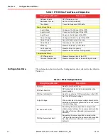
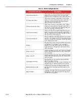
Страница 28: ... and configuration data is displayed as shown in Figure 4 4 The figure shows the information that will be displayed with the Configuration tab selected The status information in the State Power Values and Temperatures groups is displayed regardless of the tab selected Figure 4 4 SPS 500 ConfigurationData The SPS data presented in the State Power Values and Temperatures groups is described in Table...

Страница 29: ...PU Temperature Measured temperature of the CPU Converter Temperature Measured temperature of the switching converter Table 4 1 SPS 500 States PowerValues and Temperatures Group Group Member Description Table 4 2 SPS 500 ConfigurationData Group Group Member Description SPS On Select to turn the SPS on SPS Auto Start On SPS output will be turned on immediately when power applied OR ing Controller On...

Страница 30: ...t will turn off for two seconds and then turn on again for the number of times specified by the Retries parameter Retries Specifies the number of times the SPS 500 firmware will attempt to turn on again in an overcurrent situation If the retry limit is reached the SPS 500 output will remain off Ignored if Overcurrent Latch Off is unchecked Relay Control A Use this pull down to select which faults ...

Страница 31: ...onfigured output voltage Output Over Voltage Fault SPS 500 output voltage is above 103 of the configured output voltage Output Overcurrent Warning The value specified by DC Overcurrent Warn on the Configuration tab has been reached or exceeded on the primary output Output Overcurrent Fault SPS 500 primary output current is above the configured DC overcurrent shutoff value Output On The SPS 500 is ...

Страница 32: ...selected Valid output voltage ranges for each overcurrent limit are also shown in the table A typical power curve showing the allowable configuration of the SPS 500 based on the overcurrent levels and voltages listed in the table is shown in Figure 4 5 The SPS 500 has an accuracy of 10 when detecting overcurrent conditions i e the SPS 500 may enter overcurrent at a value that differs up to 10 from...

Страница 33: ...ows SPS output will be on for 20 milliseconds SPS output will be off for 2 seconds SPS output will be on for 20 milliseconds SPS output will be off for 2 seconds This back off and retry behavior will repeat until the overcurrent situation is corrected or until the number of configured Retries is exceeded if Overcurrent Latch Off is enabled This pattern is illustrated in Figure 4 6 Figure 4 6 SPS 5...

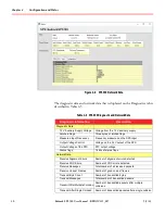
Страница 34: ... then selecting the Apply Changes button see Figure 4 4 Diagnostic Data Selecting the Diagnostics tab displays diagnostic information from the SPS 500 as well as counters for sent and received network data Figure 4 7 shows the diagnostic information that is displayed when the Diagnostic Data heading is expanded on the Diagnostics tab Figure 4 7 SPS 500 Diagnostic Data Figure 4 8 shows the counter ...

Страница 35: ...red on the SPS input Output Voltage Control Voltage on the 24 V output of the SPS Output Voltage of the PFC PFC output voltage Status flags 16 bits of status flags Network Data Receive Alignment Errors Number of alignment errors detected Receive CRC Errors Number of CRC errors detected Receive Messages Total number of all received packets Receive Unicast Frames Number of good unicast frames Transm...

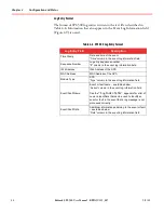
Страница 36: ...SPS 500 is capable of storing over 200 000 log messages before wraparound occurs Figure 4 9 shows an example of an SPS 500 event log Use the Log to File checkbox to save the log information to a text file on the workstation The log file will be written to a user selectable file location Provide a log file name or accept the default SPS Name Log Select the Clear Log button to reinitialize the SPS 5...

Страница 37: ...ence Number Log entry sequence number column in the event log information field IPv4 Address IPv4 Address of the SPS MAC Address MAC Address of the SPS Module Type SPS Type column in the event log information field Event Fault Name Event or fault name see tables below Action column in the event log information field See the Log Index Table appendix for a list of numeric identifiers that can be use...

Страница 38: ...Connection was accepted via OPC UA or Bedrock IDE IPv4 or IPv6 address of the client Client Disconnect Connection was terminated via OPC UA or Bedrock IDE IPv4 or IPv6 address of the client Authentication Failure A client attempting a connection has failed to authenticate IPv4 or IPv6 address of the client plus the subject name sent by the client Log Erase The log was erased The Log Erase entry wi...

Страница 39: ...ercurrent Limit SPS 500 revision B or later 18 OR ing Overcurrent Warn SPS 500 revision B or later 19 Total Overcurrent Warn SPS 500 revision B or later Table 4 9 SPS 500 Logged Faults Fault Name Fault Reason Additional Fault Data Input Under Voltage The input voltage has fallen below the operational requirement Input voltage in volts Internal Fault An internal power conversion fault has been dete...

Страница 40: ...current Limit OR ing output current in amps Total Output Overcurrent Fault The sum of the load on the primary output and OR ing output is greater than the configured Total Overcurrent Limit Total output current in amps Table 4 9 SPS 500 Logged Faults Fault Name Fault Reason Additional Fault Data Table 4 10 Additional SPS 500 Logged Items Log Entry Text Reason Additional Data Output Overcurrent War...

Страница 41: ...set of data received at the configured Snapshot Interval First message with snapshot data contains the following data Input Voltage V Input Current mA Input Power W Output Voltage V Output Current mA Output Power W Efficiency Line Frequency Hz CPU Temperature degrees C SPS Snapshot 2 The second set of data received at the configured Snapshot Interval Second message with snapshot data contains the ...

Страница 42: ...r information on configuration of the BedrockLogMonitor service and an ODBC database Updating SPS Firmware Selecting the Update Firmware button in the Device Management window Figure 4 2 will start the Bedrock Control System Upgrade Utility For more information on the utility see the Bedrock IDE online help OPC UA In addition to the connection to the Bedrock IDE the SPS 500 supports one OPC UA con...

Страница 43: ...PS Watts RO Enabled Turns the SPS on or off RO Output Voltage Voltage on the 24 V output of the SPS Volts DC RO Output Current Output current on the main DC output Amps RO Output Power Output power from the SPS Watts RO Efficiency Calculated efficiency of the SPS Percent RO Line Frequency Measured frequency of the AC input Hertz RO CPU Temperature Measured temperature of the CPU Degrees Celsius RO...

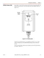
Страница 44: ...PS 500 health and network activity The SPS 500 has three status LEDs as shown in Figure 4 10 Figure 4 10 SPS 500 Status LEDS The Ethernet Link LED indicates a good Ethernet link when it is on solid yellow The Ethernet Activity LED will blink whenever there is Ethernet activity The Tri color SPS Status LED provides information about SPS 500 health as described in Table 4 12 ...

Страница 45: ...t 5 Orange 1 blink Repeats while condition persists Output overcurrent 6 Red 3 blinks Repeats while condition persists Input frequency out of range 7 Orange 2 blinks Repeats until fault cleared PWM fault 8 Blue 4 blinks Repeats for 10 seconds Image update validation failed 9 Orange 3 blinks Does not repeat Authentication failure 10 Green Red Status LED is green with 1 red blink per cycle Repeats w...

Страница 46: ...z Inrush current typical cold start 20 amps Line regulation 100 mV Load regulation 100 mV Ripple and noise 100 mV Power factor 0 95 Main supply output holdup time 20 ms Microcontroller holdup time 1 0 seconds Standby power draw 1 2 watts Maximum load current 19 amps 26 V DC Hardware short circuit current limit 22 amps maximum see section on overcurrent behavior in Configuration and Status Output v...

Страница 47: ...ification Value Communication output ports Two Type C relay contacts rated Max switching voltage 125 V DC 150 V AC Max switching current 1 amp resistive load One 10 100 Ethernet port with IEEE 1588 timestamp Status Indicators Tri color status LED See the SPS 500 Status LEDs States table in the Configuration and Status chapter Yellow Ethernet link LED On indicates Ethernet link Yellow Ethernet acti...

Страница 48: ...y FSMSPSUPS01 SPS Universal mount Bracket required for installing the SPS 500 in either a panel mount or pipe mount configuration FSMSPSUPS02 Universal Mount Strap Quantity of 3 straps for installing the SPS 500 to the pipe mount configuration FSMSPSTOP01 SPS Mounting Bracket Top Lock Required to secure the top portion of the SPS 500 to the bracket assembly FSMSPSBOT01 SPS Bottom Shroud Shroud to ...

Страница 49: ...zardous location in accordance with the following documents UL 121201 Edition 9 Nonincendive Electrical Equipment for Use in Class I and II Division 2 and Class III Divisions 1 and 2 Hazardous Classified Locations CAN CSA C22 2 NO 213 17 Nonincendive Electrical Equipment for Use in Class I and II Division 2 and Class III Divisions 1 and 2 Hazardous Classified Locations Edition 3 FCC Testing The Be...

Страница 50: ... User Manual BRDOC125_007 C 2 Requirement RS105 Radiated Susceptibility Transient Electromagnetic Field Achilles Certification The Bedrock SPS 500 has received Achilles Communication Level 2 Certification from GE Digital The SPS 500 has passed tests for network robustness ...

Страница 51: ...c identifier Table D 1 SPS 500 Log Events and Identifiers Numeric Identifier Name of Event or Fault Type 1 Power Up Event 6 Configuration Change Event 7 Client Connect Event 8 Client Disconnect Event 9 Authentication Failure Event 13 Log Erase Event 18 System Time Set Event 19 Fault Reset Event 20 Network Configuration Change Misc 21 Reset Latch Off Event 22 RTC Not Valid Event 265 Over Temperatur...

Страница 52: ... Machine Interface IDE Integrated Development Environment IEC International Electrotechnical Commission IEEE Institute of Electrical and Electronics Engineers IIoT Industrial Internet of Things IP Ingress Protection International Protection Rating IP Internet Protocol IPV4 Internet Protocol Version 4 IPV6 Internet Protocol Version 6 LED Light emitting Diode mA Milliamps MAC Media Access Control MC...

Страница 53: ...io Frequency RO Read Only RTC Real Time Clock R W Read Write SPS Secure Power Supply UL Underwriters Laboratory UPS Uninterruptible Power Supply URL Universal Resource Locater VAC Volts Alternating Current VDC Volts Direct Current WO Write Only Table E 1 Table of Acronyms and Symbols Acronym Symbol Meaning ...

Отзывы: