Beckhoff ELX2002 Скачать руководство пользователя страница 17

Mounting and wiring

ELX2002 and ELX2008

17

Version: 2.0.0

NOTE

Protect the terminals against electrostatic discharge (ESD)

Electronic components can be destroyed by electrostatic discharge. Therefore, take the safety measures to
protect against electrostatic discharge as described in DIN EN 61340-5-1 among others. In conjunction with
this, ensure that the personnel and surroundings are suitably earthed.

NOTE

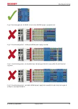
Do not place terminals on E-bus contacts

Do not place the ELX terminals on the E-bus contacts located on the right-hand side. The function of the E-
bus contacts can be negatively affected by damage caused by this, e.g. scratches.

NOTE

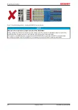
Protect the terminals against dirt

To ensure the functionality of the ELX terminals they must be protected against dirt, especially on the con-
tact points. For this reason use only clean tools and materials.

NOTE

Handling

• It is forbidden to insert conductive or non-conductive objects of any kind into the interior of the housing

(e.g. through the ventilation slots in the housing).

• Use only the openings provided in the housing front and appropriate tools to actuate the spring-loaded

terminal contacts on the front side for attaching connection cables to the terminal; see chapter 

Wiring

[

}

 25]

.

• The opening of the housing, the removal of parts and any mechanical deformation or machining of an

ELX terminal are not permitted!

If an ELX terminal is defective or damaged it must be replaced by an equivalent terminal. Do not carry out
any repairs to the devices. For safety reasons repairs may only be carried out by the manufacturer.

NOTE

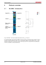
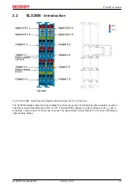
Contact marking and pin assignment

The colored inscription labels above the front connection contacts shown in the illustrations in the introduc-
tion chapter are only examples and are not part of the scope of delivery!
A clear assignment of channel and terminal designation according to the chapter contact assignment to the
actual terminal point can be made via the lasered channel numbers 1 to 8 on the left above the respective
terminal point as well as via the laser image.
Observe any possible polarity dependency of connected intrinsically safe circuits!

Содержание ELX2002

Страница 1: ...Operating manual ELX2002 and ELX2008 Two and eight channel digital output terminals 24 V DC Ex i 2 0 0 2020 03 02 Version Date...

Страница 2: ......

Страница 3: ...nditions of use for ELX terminals 16 3 2 Installation notes for ELX terminals 16 3 3 Arrangement of ELX terminals within a bus terminal block 18 3 4 Installation position and minimum distances 21 3 5...

Страница 4: ...Table of contents ELX2002 and ELX2008 4 Version 2 0 0...

Страница 5: ...dification of products that have already been supplied may be made on the basis of the data diagrams and descriptions in this documentation Trademarks Beckhoff TwinCAT EtherCAT EtherCAT G EtherCAT G10...

Страница 6: ...for trained specialists in control automation and drive engineering who are familiar with the applicable national standards Description of instructions In this documentation the following instruction...

Страница 7: ...nment extended with sensor illustration Chapter Arrangement of ELX terminals within a bus terminal block updated Chapter Marking of ELX terminals updated Technical data updated 1 4 0 Chapter Arrangeme...

Страница 8: ...mous with each revision there is usually a description ESI EtherCAT Slave Information in the form of an XML file which is available for download from the Beckhoff website The revision has been applied...

Страница 9: ...l has a unique Beckhoff Traceability Number BTN Ex marking The Ex marking can be found at the top left on the terminal II 3 1 G Ex ec ia Ga IIC T4 Gc II 1 D Ex ia Da IIIC I M1 Ex ia Ma I IECEx BVS 18...

Страница 10: ...Foreword ELX2002 and ELX2008 10 Version 2 0 0 Fig 2 ELX9560 0000 with date code 12150000 BTN 000b000 and Ex marking...

Страница 11: ...Foreword ELX2002 and ELX2008 11 Version 2 0 0 Fig 3 ELX9012 with date code 12174444 BTN 0000b0si and Ex marking...

Страница 12: ...Ex i The ELX2002 digital output terminal enables the direct connection of intrinsically safe actuators located in hazardous areas classified Zone 0 20 or 1 21 The ELX2002 supplies an output voltage of...

Страница 13: ...mA Ex i The ELX2008 digital output terminal enables the direct connection of intrinsically safe actuators located in hazardous areas classified Zone 0 20 or 1 21 The ELX2008 supplies an output voltage...

Страница 14: ...ess image 2 x 1 bit 2 x 8 bit Weight app 55 g app 100 g Dimensions W x H x D app 15 mm x 100 mm x 70 mm width aligned 12 mm app 27 mm x 100 mm x 70 mm width aligned 24 mm Permissible ambient temperatu...

Страница 15: ...off bus terminal system with functions for integrating intrinsically safe field devices from hazardous areas The intended field of application is data acquisition and control tasks in discrete and pro...

Страница 16: ...moved from the bus terminal system if all supply voltages have been switched off or if a non explosive atmosphere is ensured The connections of the ELX9560 power supply terminal may only be connected...

Страница 17: ...ing e g through the ventilation slots in the housing Use only the openings provided in the housing front and appropriate tools to actuate the spring loaded terminal contacts on the front side for atta...

Страница 18: ...to the right of an ELX9560 nor to the left of any ELX signal terminal The last terminal of each ELX segment is to be covered by an ELX9012 bus end cover unless two ELX9410 power supply terminals are i...

Страница 19: ...er supply terminal Fig 10 Invalid arrangement missing ELX9560 power supply terminal Fig 11 Invalid arrangement terminal that does not belong to the ELX series within the ELX terminal segment Fig 12 In...

Страница 20: ...9560 When configuring the ELX terminal segment please note the maximum available output current of the ELX9560 power supply terminal in accordance with the specified technical data If required an addi...

Страница 21: ...ronics through convection The direction indication down corresponds to the direction of positive acceleration due to gravity Minimum distances Observe the following minimum distances to ensure optimum...

Страница 22: ...First attach the fieldbus coupler to the mounting rail 2 The bus terminals are now attached on the right hand side of the fieldbus coupler Join the compo nents with tongue and groove and push the ter...

Страница 23: ...ons within a bus terminal block The electric connections between the Bus Coupler and the Bus Terminals are automatically realized by joining the components The six spring contacts of the E Bus deal wi...

Страница 24: ...nd simple assembly High Density Terminals HD Terminals Fig 18 High Density Terminals The Bus Terminals from these series with 16 connection points are distinguished by a particularly compact design as...

Страница 25: ...screwdriver or move it alternately don t toggle 2 The wire can now be inserted into the round terminal opening without any force 3 The terminal point closes automatically when the pressure is release...

Страница 26: ...ire per terminal point When using fine wire conductors it is recommended to connect them with wire end sleeves in order to establish a safe conductive connection In addition make sure that the pin ass...

Страница 27: ...nment Terminal point Description Name No Output 1 1 Output channel 1 2 not implemented Output 1 3 Output channel 1 4 not implemented Output 2 5 Output channel 2 6 not implemented Output 2 7 Output cha...

Страница 28: ...tput 3 4 Output channel 3 Output 2 5 Output channel 2 Output 2 4 Output channel 2 Output 4 7 Output channel 4 Output 4 8 Output channel 4 Output 5 9 Output channel 5 Output 5 10 Output channel 5 Outpu...

Страница 29: ...s kind of certification are marked by this sign 2 UL certification according to UL508 with limited power consumption The current consumed by the de vice is limited to a max possible current consumptio...

Страница 30: ...he ELX series may only be used in potentially explosive areas of Class I Division 2 Group A B C D or in non explosive areas WARNING Consider the Control Drawing ELX documentation When installing the I...

Страница 31: ...eckhoff components there Beckhoff Headquarters Beckhoff Automation GmbH Co KG Huelshorstweg 20 33415 Verl Germany Phone 49 5246 963 0 Fax 49 5246 963 198 e mail info beckhoff com Beckhoff Support Supp...

Страница 32: ...and two ELX9410 at the end of the ELX terminal segment 18 Fig 8 Valid arrangement multiple power supplies by ELX9560 each with an upstream ELX9410 18 Fig 9 Valid arrangement ELX9410 in front of an EL...

Отзывы: