background image

Adjusting the limit positions with a rotary switch or a locking button

Intelligent installation management

Limit position status indicator

A brief stopping and restarting indicates that no limit position has been set in that direction of movement.

Completion of installation following automatic setting of limit position "Stop"

The drive saves the limit position "Stop" permanently once the it has been reached 3 times in succession. Installation is then com-
plete.

Setting the limit positions

There are several ways to set the limit positions:

Extended point to retracted point

Extended point to retracted stop

If the tubular drive switches off prematurely while extending/retracting, due to an obstruc-

tion, the obstruction can be cleared by extending/retracting the screen and removing the

obstruction. The upper limit position can be set by extending/retracting again.

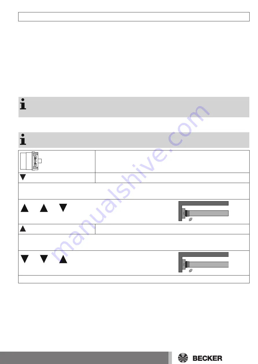
Extended point to retracted point

There is no shading solution length adjustment with this limit position setting.

Set both switches to the programming setting.

Open to the desired extended limit position.

Carry out the following sequence without interruption between the individual drive commands.

The tubular drive confirms.

1 s

1 s

until STOP and hold until

Then open to the desired retracted limit position.

Carry out the following sequence without interruption between the individual drive commands.

The tubular drive confirms.

1 s

1 s

until STOP and hold until

The limit positions are now set.

15

Содержание E12a

Страница 1: ...for sun protection systems Important information for Fitters Electricians Users Please forward accordingly These instructions must be kept safe for future reference Becker Antriebe GmbH Friedrich Ebert Straße 2 4 35764 Sinn Germany www becker antriebe com 2010 301 096 0 14 08 2018 ...

Страница 2: ...h screw connection 10 Mounting the drive in the tube 10 Setting the limit positions with the switches on the drive head 12 Deleting the limit positions with the switches 14 Adjusting the limit positions with a rotary switch or a locking button 15 Deleting the limit positions with a rotary switch or a locking button 16 Setting the limit positions using the programming unit 17 Changing the additiona...

Страница 3: ...ug in connecting cable Please observe these Assembly and Operating Instructions when installing and setting up the equipment The date of manufacture comes from the first four digits of the serial number The numbers 1 and 2 indicate the year and the numbers 3 and 4 indicate the calendar week Example 24th calendar week in 2012 Ser No 1224XXXXX Explanation of pictograms CAUTION CAUTION indicates a ha...

Страница 4: ... of safety instructions is not exhaustive since it would be impossible for the standard to include all sources of danger For example the design of the operated product the way the drive works in the situation it is installed in or even the way the end product is mounted in the end user s place of use cannot be taken into consideration by the drive manufacturer If any questions or uncertainties reg...

Страница 5: ...Physical injuries or damage to property can result in the event of unauthorised interventions or failure to heed warnings Be careful when touching the tubular drive as it heats up during operation for technical reasons Before installation shut down all lines and control devices that are not essential for op eration Crushing or shearing points must be avoided or protected When installing the drive ...

Страница 6: ...lways carry the drive by the housing tube Other applications uses and modifications are not permitted in order to protect the safety of the users and others since these ac tions can impair the system s safety and carry the risk of personal injury and property damage The drive manufacturer does not accept liability for damages or injury arising from such actions Always observe the information in th...

Страница 7: ...wer supply to the connecting cable must be disconnected Insert a suitable flathead screwdriver between the locating lug and the snap in pin so that the snap in pin releases the locating lug from the plug Now you can pull out the connecting cable along with the flathead screwdriver dia 35 A A snap in pin 7 ...

Страница 8: ...wer supply to the connecting cable must be disconnected Insert a suitable flathead screwdriver right into the recess of the locating latch so that the latch releases the locating lug from the plug Now you can pull out the connecting cable along with the flathead screwdriver dia 45 and dia 58 1 2 A A locating latch 8 ...

Страница 9: ...sponsible electrical contractor Calculate the space required at the side M by measuring the drive head 1 and wall bracket 2 The clear dimension of the box X minus the space required at the side M and idler G gives the length L of the barrel L X M G The space required at the side M varies depending on the combination of drive and wall bracket Then mount the wall bracket and idler Ensure that the ba...

Страница 10: ...pter with separate drive adapter safety catch Assembling and disassembling the drive adapter with screw connection Mounting the drive in the tube For profile tubes In the case of some drive adapters tolerances of the groove widths in different bar rels can be offset by rotating the drive adapter into a different groove recess These groove recesses have different sizes and allow the drive to fit ex...

Страница 11: ...elf tapping screw dia 6 3 x 13 mm We also recommend screwing the idler to the barrel Attention Do not hammer the tubular drive into the tube or drop it into the barrel Assemble the tubular drive with the relevant ring 1 and drive adapter 2 If the ring has several grooves select the groove which is a perfect fit and push the ring 1 onto the thrust ring Insert the tubular drive with the pre assemble...

Страница 12: ...o retracted point Extended point to retracted stop The limit position becomes fixed after the tubular drive has turned off automatically in the desired position three times If the tubular drive switches off prematurely while extending retracting due to an obstruc tion the obstruction can be cleared by extending retracting the screen and removing the obstruction The upper limit position can be set ...

Страница 13: ...retracted limit position Now change the setting of the retracting direction of rotation switch from the delete setting to the programming setting The limit positions are now set Extended position to retracted stop Set both switches to the delete setting Execute a short drive command Open to the desired extended limit position Change the setting of the extending direction of rotation switch from th...

Страница 14: ...ned Change the setting of the switch of the relevant limit position from the programming setting to the delete setting Execute a short drive command The limit position is now deleted Deleting both limit positions Any additional functions that may have been set are deleted at the same time or are reset to the factory default settings Reset both switches from the programming setting to the delete se...

Страница 15: ...witches off prematurely while extending retracting due to an obstruc tion the obstruction can be cleared by extending retracting the screen and removing the obstruction The upper limit position can be set by extending retracting again Extended point to retracted point There is no shading solution length adjustment with this limit position setting Set both switches to the programming setting Open t...

Страница 16: ...tus in dicator LSI must be displayed before the limit position is reached The tubular drive switches off automatically The limit positions are now set Deleting the limit positions with a rotary switch or a locking button The switching commands sequence must be carried out in quick succession Any addi tional functions that have been set are retained Carry out the following deletion sequence without...

Страница 17: ...nt Extended point to retracted stop The limit position becomes fixed after the tubular drive has turned off automatically in the desired position three times If the tubular drive switches off prematurely while extending retracting due to an obstruc tion the obstruction can be cleared by extending retracting the screen and removing the obstruction The upper limit position can be set by extending re...

Страница 18: ...en to the desired retracted limit position Press the programming button of the programming unit for 3 seconds The tubular drive confirms The limit positions are now set Extended point to retracted stop with programming unit Set both switches to the programming setting Open to the desired extended limit position Press the programming button of the programming unit for 3 seconds The tubular drive co...

Страница 19: ...sition must be set in order to adjust the stop behaviour The stop behaviour can be changed during the first 3 runs towards the stop Press the retract button in order to retract the sun protection system While retracting also press the programming button until the tubular drive switches off automatically at the stop and continue holding the two buttons down until con firmation is complete Confirmat...

Страница 20: ...e Deleting a limit position when 2 limit positions are programmed Any additional functions that have been set are retained black brown blue green yellow black brown blue green yellow Programming button Travel button Open close to the limit position to be deleted Press the programming button and keep it pressed Then press down the travel button and keep it pressed Now release the programming button...

Страница 21: ...en close the shading solution to a point between the limit positions Press the programming button and keep it pressed Then press down the travel button and keep it pressed Now release the programming button but continue to keep the travel button pressed Next press the programming button again The tubular drive confirms Both limit positions are deleted 21 ...

Страница 22: ...number of cycles an awning is capable of depends on the barrel diameter and awning extension The drive running time is cut short if the drive has not cooled down fully after the previous use Start point to retracted stop Retract Extend Set both switches to the programming setting Use the operator control to move the sun protection system to the desired maximum projection This must be at least 2 5 ...

Страница 23: ...interruption until the tubular drive switches off automatically Installation is now complete electronic limit switching has saved the limit positions As a final check run the sun protection system to the two limit positions again To ensure that the limit position is reliably detected and the sun protection system is fully closed the tubular drive pulls the cloth slightly more strongly during the i...

Страница 24: ...ction with the programming unit On delivery the fabric tensioning function is deactivated Activating the fabric tensioning function To activate it move to the Extend limit position Press the programming button for approx 5 seconds Confirmation is provided by a shift Now move to the position where the fabric has the desired tension Press the programming button for approx 5 seconds Confirmation is p...

Страница 25: ...used in the same system The changeover time for switching the running direction must be at least 0 5 s The switch and control must not execute simultaneous UP and DOWN com mands Protect the electrical connections from damp Once you have finished wiring everything to the control ALWAYS check the right direction assignment of the drive to the control buttons UP and DOWN EXTEND and RETRACT If the dri...

Страница 26: ...otection IP 44 Min tube inside diameter mm 47 Emission sound pressure level dB A 70 Technical data dia 58 Tubular drive L60 11 L80 11 L100 11 Model E12a Type C PS V1 A Rated torque Nm 60 80 100 Output speed rpm 11 11 11 Limit switch range 64 revolutions Supply voltage 240 V AC 50 Hz Connected load W 250 310 450 Rated current consumption A 1 05 1 30 1 95 Operating mode S2 4 min Degree of protection...

Страница 27: ...lace the tubular drive When you attempt to set the limit positions using the program ming unit this does not work The limit positions were previously set using the switches Set both switches to the delete setting Execute a short drive command Set both switches to the programming setting simultaneously Re set the limit positions using the programming unit When you attempt to set the limit positions...

Страница 28: ...Sample wiring diagram Controlling one several drive s via a single switch button Controls black brown blue green yellow Controls 28 ...

Страница 29: ...29 ...

Страница 30: ...30 ...

Страница 31: ...31 ...

Страница 32: ......

Отзывы: