background image


20 

BA_BM_AM-400-500-1200_EN_46-21.docx


10


Vacuum Clamping Unit (Option) 

The optionally available Vacuum Clamping Unit allows workpieces to be fixed quickly and securely. The heart of 
the system is the electric vacuum pump with vacuum tank and automatic switch-off, which and which can be 
placed either on the workshop floor or optionally under the table top on the lower shelf. For reliable and safe 
operation, the vacuum pump is supplemented with an optional foot switch, which is used to unclamp the suc-
tioned workpieces. 


The vacuum pump is an electrically operated auxiliary device. 


The vacuum pump must not be operated on wet or damp ground.  


There is a risk of short circuit with increased risk of injury! 


Maintenance and repair work on the vacuum pump may only be carried out by authorised 
electricians in accordance with the electrical regulations. 


If the connection plug is damaged or the insulation is defective, switch off the vacuum pump 
immediately and have it repaired.  


In the event of a power failure or failure of the vacuum pump, there is a risk of workpieces 
falling down. Therefore, generally wear safety shoes with steel toecaps. 


Caution: Danger of tripping! Lay the power supply cables and vacuum hoses so that they do 
not pose a trip hazard and mark them with black and yellow marking tape if necessary.  

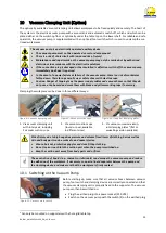
Clamping the workpiece can be done in three different ways: 


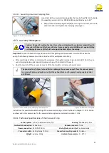
Figure 8: Vacuum clamping unit


Figure 9: Vacuum suction cups


Figure 10: Universal clamping plates 


1.


Via vacuum clamping unit  
with rotary axis, including  
2 vacuum suction cups. 

2.


Via vacuum suction cups 
(round or oval, available  
in different sizes) 

3.


Via vacuum universal alumin-
ium clamping plates

3

 (flat or 

swivelling version available)  


Risk of injury due to high negative pressure and volume flow! Items of clothing, hair as well as 
skin and body parts can be sucked in and cause injuries. 


Wear a hair net, protective goggles and close-fitting clothing. 


Do not look or reach into the suction port when the pump is switched on. 


Keep the suction port away from body parts and orifices. 


The penetration of liquids (e.g. coolants or lubricants) can damage the vacuum pump and reduce 
the adhesion of the workpiece. If necessary, connect a liquid separator between the pump and 
the clamping device and make sure that the workpiece is firmly seated. 

10.1


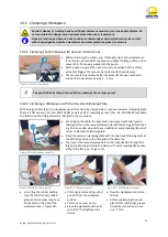
Switching on the Vacuum Pump


 Figure 11: Vacuum main switch 

Before  starting  up,  make  sure  that  all  vacuum  hoses  between  vacuum 
pump, foot switch and clamping device are correctly connected and that 
the vacuum clamping unit is properly fixed to the supporter. The vacuum 
pump can then be switched on:


Plug the earthed plug into a power socket (230 VAC)


Switch on the vacuum pump with the switch (S) on the earthed plug


3

 Can only be mounted on supporters with a hole grid table top. 

S

Содержание Supporter AM 1200 FH

Страница 1: ...76 962 978 0 Fax 49 0 7576 962 978 90 E Mail info beck maschinenbau de Web https www beck maschinenbau de Operating Manual Height adjustable Work and Assembly Benches Supporter AM 500 FH and AM 1200 FH Supporter AM 400 ESA and AM 500 ESA Valid for Supporter types AM 500 FH and AM 1200 FH AM 400 ESA and AM 500 ESA ...

Страница 2: ...Modifications of Supporter 9 4 6 Load Distribution and Influence on the Nominal Load 9 4 7 Hazardous Areas 10 4 8 Residual Risks 11 4 9 Observe the Environmental Protection Regulations 11 4 10 Organisational Measures 12 4 11 Personnel Selection and Qualification Basic Duties 12 5 Technical Specifications 13 5 1 Manufacturer and Nameplate 13 6 Transport to the Installation Site 14 6 1 Unloading the...

Страница 3: ...er Accessories 29 15 4 AM 500 FLEXX FH and AM 1200 FLEXX FH 30 15 4 1 Table Tops for AM 500 1200 FLEXX FH 31 EU Declaration of Conformity 32 List of Figures Figure 1 Permissible load with load distribution 9 Figure 2 Nameplate 13 Figure 3 Transport to installation site 14 Figure 4 Basic equipment AM 500 FH AM 1200 FH 16 Figure 5 Basic equipment AM 400 ESA AM 500 ESA 17 Figure 6 Food pedal for heig...

Страница 4: ...e sense of these instructions means the installation and commissioning the operation and proper usage the influence on operating conditions as well as the maintenance troubleshooting and repair Apart from the operating manual and the legally binding accident prevention provisions applicable in the country and place of use the recognized technical regulations for safe and proper work must also be o...

Страница 5: ...rence to a prohibited zone on a platform Do not enter There is an increased risk of injury or even death Reference to a possible crushing hazard Non observance increases the risk of injury to hands and fingers Reference to a possible crushing hazard Non observance increases the risk of injury to feet and toes Possible dangerous crushing hazard in the area of stationary objects Risk of personal inj...

Страница 6: ...ise height adjustment for ergonomic working as well as high flexibility and mobility are of particular importance The supporter must not be used for work that does not correspond to its intended use see section 4 3 3 Target Group and Previous Experience This operating manual is intended for the operating and maintenance personnel of the work and assembly bench The operating personnel is to be dete...

Страница 7: ... necessary Repair and maintenance work on electric hydraulic and pneumatic components e g electric drives hy draulic cylinders vacuum pumps etc may only be performed by authorized and trained personnel Maintenance must be carried out and documented in accordance with the maintenance instructions For repairs only original spare parts from the manufacturer may be used Only instructed trained or qual...

Страница 8: ...porter may only be used on horizontal floors for lifting loads The supporter may only be moved when the load is lowered The supporter must be positioned freely in the room when lifting and lowering This means that no shearing or crushing edges may be caused by the movement of the work and assembly bench The maximum load see 5 Technical Specifications with load center in the middle of the supporter...

Страница 9: ...see 15 may be used Deviations are not permitted Unauthorized modifications or conversions by the operator without the written consent of the manufacturer are prohibited This excludes any warranty liability and other claims for damages by the operator against the manufacturer 4 6 Load Distribution and Influence on the Nominal Load The nominal maximum permissible load of supporter is based on a load...

Страница 10: ...aring parts seals and lines Oil spraying out with high pressure in case of damaged cylinder or seals Injuries and poisoning of the eyes Wear safety goggles or face shield Repair damaged parts and or seals immedi ately only qualified personnel Pneumatics Rear openings of the Vacuum pump Outflowing air gases and dust Injuries of the eyes Do not look into the openings wear safety goggles or face shie...

Страница 11: ...ansport or installation Unauthorised persons are not allowed to enter the supporter installation area responsibility of the operator Danger of electric shock on models with battery operated hydraulic height adjustment Work on the electrical components may only be carried out by qualified personnel Be aware of possible tripping and slipping hazards on the floor Prevent possible hazards by keeping t...

Страница 12: ...ments or conversions to the supporter without the man ufacturer s approval This will compromise safety and invalidate the manufacturer s warranty and any lia bility claim Spare parts must meet the technical requirements specified by the manufacturer The exclusive use of original spare parts ensures this Therefore only use original spare parts from the manufacturer Observe the fire alarm and firefi...

Страница 13: ... approx 135 kg approx 140 kg Hydraulic power units 1 x left 1 x left 1 x right none none Electric drives none none 1 x left 1 x right 1 x left 1 x right Connection voltage none none 230 VAC 50 Hz 230 VAC 50 Hz Type of connection none none earthed connector earthed connector 5 1 Manufacturer and Nameplate Manufacturer Reinhold Beck Maschinenbau GmbH Im Grund 23 DE 72505 Krauchenwies Germany Phone 4...

Страница 14: ...et appropriately drive centrally into the designated places on the freight pallet on the longi tudinal side of the supporter and lift carefully Carefully lift the supporter from the truck The net weight is approx 120 kg AM 500 FH approx 150 kg AM 1200 FH approx 135 kg AM 400 ESA and approx 140 kg AM 500 ESA each without accessories Check delivery condition Check for completeness and transport dama...

Страница 15: ...y for safe loading is borne by the respective shipper Please note the following when lashing in the transport vehicle The loading area of the transport vehicle must always be clean and dry The lashing straps used must be suitable for the total weight of the supporter see chapter Fehler Ver weisquelle konnte nicht gefunden werden Fastening on the loading area is done by lashing down This means that...

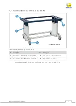
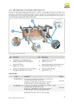
Страница 16: ...os Description Pos Description 1 Foot pedal for height adjustment 4 Support frame for table top 2 Swivel castors 2 x with brakes on front side 5 Synchronous shaft top 3 Lifting column with hydraulic cylinder 6 Synchronous shaft bottom For available table tops and shelves as well as other accessories refer to chapter 15 2 1 3 5 6 4 Article No 210 100 00 ...

Страница 17: ...SA AM 500 ESA Pos Description Pos Description 1 Push button unit for height adjustment 3 Lifting column with spindle motors 2 Swivel castors 2 x with brakes on front side 4 Support frame for table top For available table tops and shelves as well as other accessories refer to chapter 15 2 1 3 4 Article No 210 200 00 ...

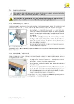
Страница 18: ... When loading or unloading the work platform the load distribution according to section 4 6 Load Distri bution and Influence on the Nominal Load must be observed and complied with A load placed on the supporter must be secured with suitable measures against slipping tipping over roll ing away and falling down This is particularly necessary for loads that have an unstable position on the plat form ...

Страница 19: ...mains in this position In order to adjust the sup porter infinitely and exactly to the desired position the foot pedal A can be released at any point By actuating the foot pedal B the platform is lowered downwards for the duration of the operation The hydraulic force is transmitted to the hydraulic cylinder s via the foot pump Foot pump and hydraulic cylin der are a fixed unit 9 4 2 AM 400 ESA AM ...

Страница 20: ...rking tape if necessary Clamping the workpiece can be done in three different ways Figure 8 Vacuum clamping unit Figure 9 Vacuum suction cups Figure 10 Universal clamping plates 1 Via vacuum clamping unit with rotary axis including 2 vacuum suction cups 2 Via vacuum suction cups round or oval available in different sizes 3 Via vacuum universal alumin ium clamping plates3 flat or swivelling version...

Страница 21: ...nal universal clamping plate There is a flat version Art No 200 405 00 as well as a 90 swivelling version Art No 200 406 00 available The fixation on the hole grid plate is identical for both versions Figure 13 Quick release coupling For fixing on the table the base plate is equipped with two fixed re taining bolts and one loose clamping bolt with matching grid hole spac ing The loose clamping bol...

Страница 22: ...unclamping the workpiece thoroughly remove chips dust and dirt from the vac uum clamping device under operating vacuum e g with an industrial hoover Only then switch off the vacuum by means of the foot switch and remove the workpiece The penetration of chips dust and dirt can damage the vacuum pump Place the vacuum pump in a clean dry place and make sure that the exhaust holes on the pump housing ...

Страница 23: ...customer service Electric spindle motor defective4 Replace spindle motor4 Control pane defective ESA versions Contact customer service Models with Vacuum Clamping Unit Fault Possible Cause Remedy Operating vacuum is not achieved or is too weak and the pump runs without inter ruption Dust chips dirt between workpiece and clamping device Remove contamination Vacuum hoses leaking Replace vacuum hoses...

Страница 24: ...umatic and hydraulic components may only be carried out by authorised and trained personnel Before any maintenance and repair work is carried out chapter 4 Safety must be read carefully and observed 12 1 Maintenance Intervals Interval Action Daily Check all components for damage and have them replaced by competent personnel if neces sary If you have any questions please contact our support phone 0...

Страница 25: ...l protection laws in force at the place of use regarding the disposal of industrial solid waste toxic and hazardous waste Hoses and plastic parts as well as other components that are not made of metal must be dismantled and recycled or disposed of separately Electrical components such as cables switches connectors transformers etc must be re moved and if possible recycled or otherwise disposed of ...

Страница 26: ...t approx 30 kg 210 300 00 HOLE GRID TABLE TOP BEECH MULTIPLEX Suitable for supporter AM 500 screwed onto platform plate is coated with linseed oil Platform size 1600 x 790 x 30 mm Holes Ø 22 mm Grid hole pitch T 100 mm Weight approx 29 kg 210 310 00 TABLE TOP BIRCH MULTIPLEX BOTH SIDES HPL COATED Suitable for all supporter versions screwed onto platform Platform size 1600 x 790 x 30 mm Colour RAL ...

Страница 27: ...ng work Phosphated surface Size 1600 x 1200 x 65 mm Thickness 4 mm Weight approx 96 kg Side wall H 65 mm Holes Ø 28 mm Diagonal grid T 100 mm 200 616 00 STAINLESS STEEL TABLE TOP SMOOTH Suitable for all supporters screwed onto beech multiplex table top with all round bevelling 20 mm on all 4 sides Size 1600 x 790 x 32 mm Thickness 2 mm Weight approx 48 kg 210 318 00 SIDE STOP RAILS 90 Suitable for...

Страница 28: ...e workpiece Optional for electric vacuum pump in carrying box Art No 210 440 00 and 210 450 00 Function 3 2 way valve Weight approx 2 kg 210 455 00 VACUUM SUCTION CUP OVAL Suitable for the rotary axis With the vacuum system the vacuum grippers are interchangeable by means of the quick change system Infinitely height adjustable 200 mm Weight approx 3 kg 210 341 00 300 x 100 mm 210 359 00 300 x 100 ...

Страница 29: ... 2 kg 210 606 00 EQUIPMENT SUPPORT RAIL Suitable for all supporters mounted on overhead unit C Rail 30 x 32 x 2 mm 1800 mm long Weight approx 10 kg 210 601 00 MULTIPLEX TOOL BASE CABINET WITH 2 DRAWER BLOCKS Suitable for all supporters incl 6 drawers Outer dimensions body W x H x D 1100 x 370 x 500 mm 2 x Drawers 620 x 40 x 420 mm 1 x Drawer 620 x 120 x 420 mm 2 x Drawers 360 x 40 x 420 mm 1 x Dra...

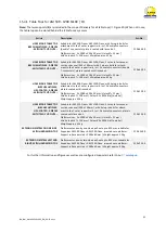
Страница 30: ... see 15 2 Hole Grid Table Top option see 15 4 1 5 Vacuum Clamping Unit with Vacuum Pump and Foot Switch option see 15 2 3 Supports are included in the scope of delivery for optional Table Tops see 15 4 1 6 Vertical Support left right option see 15 Article Numbers Article Description Art No AM 500 FLEXX FH Load capacity up to 500 kg with 1 lifting unit in the left column including storage shelf und...

Страница 31: ... Suitable for AM 500 Flexx AM 1200 Flexx with 4 plug in bolts for attachment to the 2 outer support rails incl 2 dovetail connectors plate is coated with linseed oil Platform size 2 x 2000 x 500 x 30 mm Holes Ø 22 mm Grid hole pitch T 100 mm Colour RAL 9016 traffic white Weight approx 42 kg 210 312 00 HOLE RIDGE TABLE TOP BIRCH MULTIPLEX HPL COATED 2 PIECES WITH TWO CUT OUTS Suitable for AM 500 Fl...

Страница 32: ...00 ESA AM 500 ESA Type designation Lifting Table Serial number s Year of manufacture in the version provided complies with the EU Machinery Directive 2006 42 EC and the following further directives The following harmonised standards and instructions have been applied in manufacturing the machine EN ISO 12100 2010 Safety of machinery General principles for design Risk assessment and risk reduction ...

Отзывы: