background image


www.beast-tek.com

            Microbe Build Guide 

Page 8 


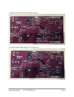
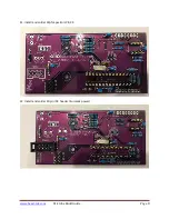
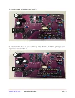
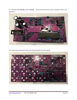
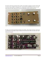
11. Install and solder 22pf capacitors C8, C9 


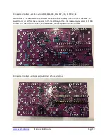
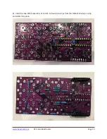
12. Install and solder 10 pin IDC header (Eurorack power) 


Содержание MICROBE v1.2

Страница 1: ...www beast tek com Microbe Build Guide Page 1 MICROBE v1 2 BUILD GUIDE www beast tek com ...

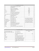
Страница 2: ...ed Brown 4 R3 R7 R10 R14 R16 100K Ohm Resistor 1 Brown Black Black Orange Brown 5 R13 R15 R17 R18 200K Ohm Resistor 1 Red Black Black Orange Brown 4 R5 R8 R9 1M Ohm Resistor 1 Brown Black Black Yellow Brown 3 JP1 JP2 8 Way Pin Header Single Row FEMALE 2 EXPAND 4 Way pin header dual Row MALE 1 ICSP ICSP do not populate POWER Shrouded 10pin 2x5 IDC Header Eurorack Power 1 Microbe IO Board BOM R5 R6 ...

Страница 3: ...www beast tek com Microbe Build Guide Page 3 1 Install and solder 10K resistors R2 R6 R11 and R12 2 Install and solder 100K resistors R3 R7 R10 R14 R16 ...

Страница 4: ...www beast tek com Microbe Build Guide Page 4 3 Install and solder 200K resistors R13 R15 R17 R18 4 Install and solder 1M resistors R5 R8 and R9 ...

Страница 5: ...www beast tek com Microbe Build Guide Page 5 5 Install and solder 1K resistor R4 6 Install and solder the inductor R1 ...

Страница 6: ...beast tek com Microbe Build Guide Page 6 7 Install and solder power diodes and IC sockets cut sockets from machine pin strips using a sharp craft knife or side cutters 8 Install and solder 20 mhz crystal Q1 ...

Страница 7: ...www beast tek com Microbe Build Guide Page 7 9 Install and solder 100nf capacitors C1 C4 C5 C6 C7 C11 10 Cut 2 x 4 pins from the male pin header strip and solder into the expand header ...

Страница 8: ...www beast tek com Microbe Build Guide Page 8 11 Install and solder 22pf capacitors C8 C9 12 Install and solder 10 pin IDC header Eurorack power ...

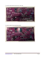
Страница 9: ...e Build Guide Page 9 13 Install and solder IC4 79L05 and the 3 x 2n3904 transistors IMPORTANT make sure you sort the 79L05 from the transistors before installation and soldering 14 Install and solder IC2 7805 voltage regulator ...

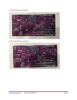
Страница 10: ...m Microbe Build Guide Page 10 15 Install and solder 100uf capacitors C2 and C10 16 Install and solder 22uf capacitor C3 Cut 2 x 8 pin sections from the MALE header pin strip and solder in place on reverse side of board ...

Страница 11: ...ek com Microbe Build Guide Page 11 17 Insert the ATMEGA328p and the MCP602 be careful to make sure they are installed in the correct direction 18 Install and solder the 1K resistors R5 R6 R7 R8 R9 R10 R11 and R12 ...

Страница 12: ... Resistors R19 R20 and R21 are positioned extremely close to some of the jacks To prevent short circuit from these resistors to the metal body of the jacks make sure you solder R19 R20 and R21 from the TOP of the board so the entire leg can be clipped off on the bottom 20 Install and solder the IC sockets cut from machine pin strips ...

Страница 13: ...www beast tek com Microbe Build Guide Page 13 21 Install the two 100nf capacitors C1 and C2 Cut two 8 pin strips from the FEMALE header pin strip and solder into place ...

Страница 14: ... Guide Page 14 22 Install the potentiometers being careful to place the T18 knurled shaft to the correct location IMPORTANT DO NOT SOLDER THE POTS they will sit happily in place for now 23 Install the thirteen jacks DO NOT SOLDER YET ...

Страница 15: ...LLY flip together then solder ONLY THE GROUND PIN of the jacks to hold them in place DO NOT solder the other jack pins AND DO NOT solder and of the pots YET 25 Once one pin of the jacks has been soldered they will stay in place Remove the clear acrylic panel and install two of the 6mm M3 screws and attach the 11mm brass stand offs on the other side Install the two remaining IC s ...

Страница 16: ...ce over the jacks and pots and wiggle things into place so the panel sits nicely DON T put any nuts on the jacks or pots yet First push the big 10mm LED via its leads through the panel Next work through the eight 3mm leds pushing them through one by one so they are flush with the panel If you put any nuts on the jacks or pots you will need to remove them so that the LEDs can be pushed through the ...

Страница 17: ...e jacks giving each one a wiggle as tightening up so that they all sit flush Give everything a final wiggle and make sure everything is seated well The panel and sockets are still reasonable flexible until everything is soldered in Once you are happy that everything is seated correctly and flush flip the panel over and solder all of the remaining jack pins and the pots and LEDs into place 29 Take ...

Страница 18: ...www beast tek com Microbe Build Guide Page 18 30 Double check and make sure everything is correct and looks right Once you are happy its time to power on and test ...

Страница 19: ...www beast tek com Microbe Build Guide Page 19 ...

Отзывы: