


34
Part No. 6-847684-00 Rev. D01
Operation
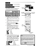
Start-Up and Checking
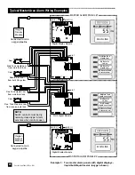
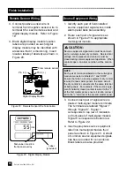
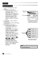
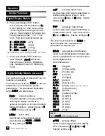
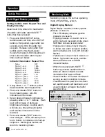
Digital Display Module
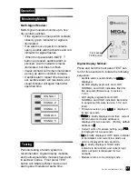
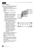
Multi-Signal Module
Status LED
Indicators
LED Display
SIGNAL #1
SIGNAL #2
SIGNAL #3
SIGNAL #4
SIGNAL #5
Status LED
Indicators
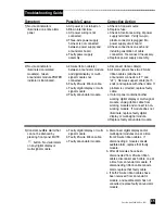
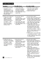
NOTE:
If any module appears to be malfunctioning, refer
to
Troubleshooting Guide
.
1. Turn on electrical power to alarm
panel.
2. Make following observations:
• POWER ON light illuminates on
front of alarm panel.
• Digital display and multi-signal
modules warm-up for ten seconds.
During warm-up, no audible or
visual alarms activated. After
warm-up, audible and visual
alarms are initiated for any active
alarm.
3. Press MUTE
button to silence
audible alarm.
4. Pressurize piping system (medical gas
and vacuum).
5. Make following observations:
• Digital display modules display
actual pipeline pressures or
vacuum levels.
• If digital display module pipeline
pressures and vacuum levels are
within pre-set limits, NORMAL
indicator is illuminated.
• If digital display module pipeline
pressures and vacuum levels are
outside pre-set limits, status
indicators show HIGH or LOW.
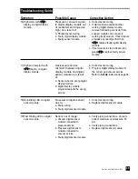
• If a fault code is displayed (
-- FF 11 --
,
-- FF 2
2 --
,
-- FF 33 --
or
-- FF 44 --
) refer to
Troubleshooting Guide
.
• Multi-signal modules indicate
current status from dry-contact
switches. Unused signals can be
disabled. Refer to
Set-Up
Procedure
.
Содержание MEGA 2
Страница 54: ...54 Part No 6 847684 00 Rev D01 Notes...
Страница 55: ...55 Part No 6 847684 00 Rev D01 Notes...


