


10
11
4.5
Installation and handling of the LEDs
It is possible to freely position the LED lighting supplied in the case to suit your system setup by affixing and
connecting the adhesive strips. The LED strips must be connected to connector “E” on the PCB panel.
Description of the LEDs
The LED lighting included in the scope of delivery is controllable in several modes of color and operation.
Connector “D” on the PCB panel can be used to connect additional LED lighting strips up to a maximum of 24
watts for lighting the interior of the case. It is also possible to link the LED strips supplied directly together and
in this way extend them.
WARNING! Only 12V LEDs may be connected.
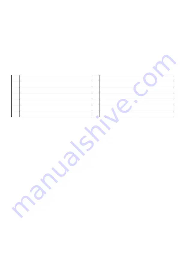
In manual mode by briefly pressing switch “D” on the front panel it is possible to cycle through the colors.
When “breath mode” is enabled there is an intermediate step between each color.
1
White
8
Blue breath
2
White breath
9
Orange
3
Red
10 Orange breath
4
Red breath
11 Purple
5
Green
12 Purple breath
6
Green breath
13 Breath mode alternately in all colors
7
Blue
14
LEDs off
Synchronized operation
To toggle between manual and synchronized operation hold down switch “D” on the front panel for about three
seconds.
In synchronized operation, connector “C” on the LED controller PCB is connected to the socket designated for
RGB LED on the motherboard. The integrated lighting is then controlled by the motherboard, with the same
range of colors.
For information about operation of the LED controller of your motherboard please refer to the motherboard
handbook.
4.6 Charging station for Qi enabled devices
The preinstalled charging station provides contactless charging of any device that conforms to the Qi standard.
If your device (e.g. your smartphone) is so equipped you can charge your device by simply placing it on area “I”
on the top of the case, without the need to plug it in.
In so doing, make sure you place the device so that its charge receptor is positioned centrally on charging
surface “I”.
Содержание dark base pro 900
Страница 1: ...1 USER MANUAL rev 2...


