2. Besides the installed PCIex16 video card with its monitor connection, if you also have another
dedicated monitor connected to one of MX310H’s video ports, both monitors will have video
outputs once the system entered Windows 10 desktop (after the Intel video driver and the
PCIex16 video card driver are installed).
3. If there is only one video output, or you want to assign the video output to different video port
(connected with its dedicated monitor), the adjustment can be made through Windows
“Display Settings” or “Intel Graphics Command Center” (
preferred
, it can be obtained through
Microsoft Store, and be installed after the Intel video driver is installed).
3. Boot Mode
1. The default boot mode is set as “UEFI”. If you want to switch the boot mode to “Legacy”, it
Can be changed through BIOS option “Boot”->”Boot Mode Select”. Then save and exit BIOS
once in order for the new boot mode to take effect.
4. PXE Boot
A. In “UEFI” mode:
1. Under BIOS option “Boot”->”Boot mode select”; change it to “UEFI”.
2. Under BIOS option “Boot”->”LAN PXE Boot Option ROM”; change it to “Enabled”.
3. Under BIOS option “Advance”->”Network Stack Configuration”:
a. Change “Network Stack” to “Enabled”.
b. Enable “Ipv4 PXE Support”.
4. Save and exit BIOS.
5. After system reboot, enter BIOS again.
6. Under BIOS option “Boot”->”UEFI NETWORK Drive BBS Priorities”, set the desired PXE LAN port
as “Boot Option #1”.
7. Press “ESC” key to get back to “Boot” menu.
8. Under BIOS option “Boot”->”Boot Option #1”; change the 1st boot device to the desired PXE
LAN that selected under step 6.
9. Save and Exit BIOS.
10. The device will show the MAC address, and display message “Start PXE over IPv4…”, which
means the UEFI mode PXE is established with PXE server.
B. In “Legacy” Mode:
1. Under BIOS option “Boot”->”Boot mode select”; change it to “Legacy”.
2. Under BIOS option “Boot”->”LAN PXE Boot Option ROM”; change it to “Enabled”.
3. Save and exit BIOS.
4. After system reboot, enter BIOS again.
5. Under BIOS option “Boot”->”NETWORK Drive BBS Priorities”, set the desired PXE LAN port as
“Boot Option #1”.
6. Press “ESC” key to get back to “Boot” menu.
7. Under BIOS option “Boot”->”Boot Option #1”; change the 1st boot device to the desired PXE
LAN that selected under step 5.
8. Save and Exit BIOS.
9. The system shall rebooted, and display the MAC address, and some message like “PXE-E79:
NBP…”, which means the legacy mode PXE is established with PXE server.
5. The Header “SPKR”
1. BIOS option “AMP SE-Input Stereo-Output Gain select” supports volume control of speaker
header “SPKR”.
6. The Header “F_AUDIO”
1. The front audio Header “F_AUDIO” volume can be adjusted through OS volume control.
Содержание MX310H
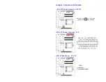
Страница 8: ...Front Panel Connector F_PANEL CPU Fan Connector CPU_FAN System Fan Connector SYS_FAN...
Страница 9: ...I2C Header I2C SMBUS Header SMBUS...
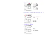
Страница 12: ...Serial Port A COMA COM Port 12V 5V Power Select COMA_PW COMB_PW COMC_PW Clear CMOS Header CLR_CMOS...
Страница 13: ...GPIO Header GPIO Front Audio Header F_AUDIO Audio AMP Output Connector SPKR...
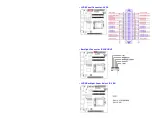
Страница 14: ...LVDS Panel Connector LVDS Backlight Connector BACKLIGHT LVDS Backlight Power Select BL_EN...


