background image


                                                                     Page 34 of 62 

7.8  Interface  

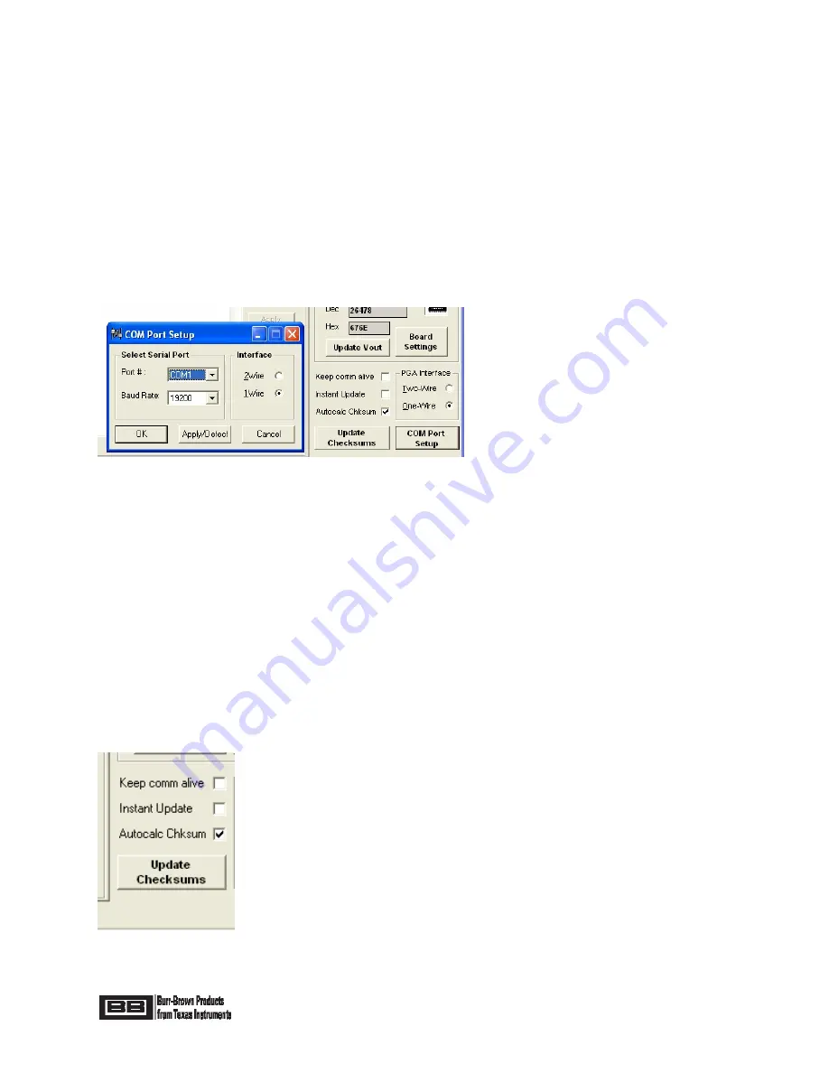
The “Interface” section in the Main Window allows for selection of One-Wire or Two-Wire digital 
communication with the PGA309 Sensor Interface Board.  Refer to Figure 24.  A single click in the respective 
circle will select the desired interface.  All Board Control Software functionality is supported over either of 
these interfaces, however the One-Wire interface is the preferred one due to potential conflicts arising from 
two Two-Wire masters (PC and PGA309) sharing the bus.  It is recommended to have PRG wire connected on 
the PGA309 Sensor Board even when using Two Wire communication.  The Board Control Software 
addresses PGA309 using One-Wire interface prior to closing the switches U10/U11.  

This stops any activity 

by the PGA309 on the Two-Wire interface for 1 second and prevents any bus conflicts.

  By pushing the 

“COM Port Setup” button a pop-up “COM Port Setup” window will appear in the Main Window.  In the pop-up 
window the desired interface may also be selected as well as which PC COM port (“Port #”) will be used and 
the Baud Rate (“Baud Rate”) for Communication through the selected COM Port.  Drop-down menus are used 
to select both the desired COM Port and Baud Rate.   Once the interface is selected it may be tested by 
pushing the “Apply/Detect” button or by pushing the “OK” button, in the pop-up window. 


Figure 24: Interface Section and COM Port Setup Pop-up Window 


7.9  Updates 

The “Updates” section (see Figure 25) in the Main Window provides options for how certain calculations and 
readings in the Main Window are updated.  If the “Autocalc Chksum” box is checked then both the 
configuration register part checksum (Checksum1) and the temperature coefficient part checksum 
(Checksum2) for the external EEPROM are computed automatically after every change.  If the box is not 
checked then the calculations of the checksums may be manually accomplished by pushing the “Update 
Checksums” button or entering the checksum values directly from hand calculation.   
 
The “Keep comm alive” box, when checked, reads the Temp ADC register and updates the Main Window 
reading about every 0.75 second, depending upon the operating system used.  This will prevent the 1s timeout 
in the PGA309 from expiring thus stopping EEPROM read-back updates even if Test Pin is set low. 
 
The “Instant Update” box, when checked, updates the PGA309 Registers immediately after every bit change 
without having to push the “Write PGA309” button. Remember that unless Test pin is set high these settings 
will be overwritten by valid external EEPROM data.   


Figure 25: Updates Section 

Содержание PGA309EVM

Страница 1: ...s Kit o Evaluate PGA309 User s Sensor o Full Temperature Evaluation Software Control for Designer s Kit o Program PGA309 for Evaluation o Program PGA309 User s Sensor in Final Module o Computation Ana...

Страница 2: ...09 Sensor Calibration Spreadsheet for Microsoft Excel 38 48 10 0 General Operating Tips 47 57 11 0 PGA309EVM PC Cable Drawing 58 12 0 PGA309EVM External EEPROM Settings for Functional Test 59 Note PGA...

Страница 3: ...glish United States with the decimal symbol set to a period More information on issues related to changing regional settings is given in section 10 3 Consult factory for other operating systems 1 2 PG...

Страница 4: ...Page 4 of 62 In addition you will need to allow Macros to run in Excel Click on Tools and then click on Options Next select the tab in the Options pop up window Click on the Security tab...

Страница 5: ...Page 5 of 62 Click on the Macro Security button...

Страница 6: ...Board The PGA309 PC Interface Board communicates to a test computer through a standard RS 232 serial port via the PGA309EVM PC Cable For USA shipments an AC wall adapter is included to provide 6Vdc t...

Страница 7: ...connected Rt and Rt allow for resistors to be used in the top or bottom of the bridge sensor s excitation path for one method of measuring bridge temperature by total bridge resistance changes Jumper...

Страница 8: ...ications will use a 6Vdc 6Vdc 9Vdc lab supply and the screw terminal inputs on Tpwr U7 provides a regulated power source of either 3V or 5V selectable through JA D3 provides protection from inadverten...

Страница 9: ...re several Test Points including a 3 position one for GND provided for ease of measuring analog signals Also provided are reserved areas with plated through standard spacing 0 1 holes for miscellaneou...

Страница 10: ...power up The supply voltage on the PGA309 must decay to near zero to ensure that on power up the state of the PGA309 is set correctly With a 10 F capacitor on Vs on the PGA309 PC Interface Board and...

Страница 11: ...Page 11 of 62...

Страница 12: ...4 7k 0 01 F 0 01 F 0 01 F 0 1 F 200 0 01 F 0 01 F 0 22 F F F F 0 01 F 0 1 F 200 1k 1k ZXMP3A17E6 SN74LVC1G07 SN74LVC1G07 SN74LVC1G07 SN74LVC1G66 SN74LVC1G66 ADS1100 Texas Instruments PCF8574A ZHCS500...

Страница 13: ...Page 13 of 62...

Страница 14: ...nterface Board Factory Jumper Settings Jumper Position J1 Rt Use on board pot for bridge J2 TEST Use on board pot for bridge J3 TEST Use on board pot for bridge J4 VEXC Use PGA309 Vexc J5 TEST Use on...

Страница 15: ...e 4 PGA309 PC Interface Board Factory Jumper Settings PGA309 PC Interface Board Factory Jumper Settings Jumper Position JA 5V PGA309 operates at 5V JB PRG PRG not connected to VOUT JC 1PU Dynamic One...

Страница 16: ...Board Control Software Installation 1 The PGA309EVM Board Control Software is installed in the normal Microsoft Windows manner Close all other applications From Start button on the task bar select Ru...

Страница 17: ...ware Startup Start the PGA309EVM Board Control Software by clicking on PGA309 DK Board Interface under the Start menu All Programs PGA309 Designer s Kit as shown in Figure 6 Figure 6 PGA309EVM Board C...

Страница 18: ...Main Window will appear with a smaller pop up window in the middle of the Main Window Click Yes on the pop up window see Figure 7 If the initial software startup does not look like Figure 7 then proc...

Страница 19: ...age 19 of 62 The First Pop Up Window will disappear and the Main Window should look as in Figure 8 If it does then proceed to Section 6 5 4 and skip Section 6 5 3 Figure 8 Software Startup Main Window...

Страница 20: ...problem could be related to regional settings More information on regional settings is given in section 10 3 Figure 9 Software Startup Wrong Com Port Click on OK in the pop up window in Figure 9 Then...

Страница 21: ...two pop up windows should disappear with only the Main Window remaining as in Figure 8 Figure 11 Communication Pop up Window after COM Port Setup 6 5 4 Hardware Checkout 1 In the Main Window click on...

Страница 22: ...A309EVM Software directory typically C Program Files PGA309 Designer s Kit A pop up window will appear as in Figure 13 Click on OK Figure 13 Open File Acknowledge Pop up Window The Main window will ap...

Страница 23: ...l 0 245V to 3 976V With Over Scale and Under Scale enabled Fault Detection External Comparators Enable Fault Detect Polarity Positive Internal Comparators Disable Temperature ADC Internal Mode Continu...

Страница 24: ...ROM by clicking on Write EEPROM in the Main Window Click on Read EEPROM and then click on Read PGA309 The Main Window should look the same as in Figure 14 4 Configure ADS1100 for continuous readback I...

Страница 25: ...ll be used for this test Table 4 below details the actions and acceptable results for a pass condition of the PGA309 Sensor Interface and PGA309 PC Interface Boards Step Rtest J4 Position ADS1100 read...

Страница 26: ...been successfully completed then the PGA309 Sensor Interface Board PGA309 PC Interface Board PC Cable PGA309EVM Board Control Software are all operating correctly 7 0 Board Control Software Overview...

Страница 27: ...le 5 Main Window Top Row Control Buttons 7 1 1 General Note on Reading Writing to PGA309 and External EEPROM When you do a Write EEPROM whatever is in the Main Window will be written to the PGA309 ext...

Страница 28: ...selecting the desired format as Binary Hex or Decimal under Display Mode in the Lookup Table section See Figure 17 If the entire contents of the EEPROM is to be viewed or edited in Hex and ASCII only...

Страница 29: ...Figure 19 and discussed above 7 3 PGA309 Registers The PGA309 current internal register contents are displayed in the PGA309 Registers section of the Main Window By clicking on the Bitmap of a registe...

Страница 30: ...f in the register table and vice versa The current values of these and the PGA309 registers will be automatically updated in the Main Window following a Read PGA309 The current settings displayed in t...

Страница 31: ...Window 7 6 PGA309 Temp ADC In the PGA309 Temp ADC section of the Main Window the current Temp ADC reading will be displayed if the Convert button is pushed If a continuous update of the Temp ADC cont...

Страница 32: ...ation is performed and the subsequent readings will use the latest calibration numbers If the Read ADS1100 button is pushed a single conversion will be performed in the ADS1100 The reading will be upd...

Страница 33: ...for offset calibration Used in the ADS1100 calibration sequence by the Board Control Program 0 P3 1 Logic output of port expander port P3 PGA309 PC Interface Board U5 pin 7 Spare port expander port a...

Страница 34: ...M Port and Baud Rate Once the interface is selected it may be tested by pushing the Apply Detect button or by pushing the OK button in the pop up window Figure 24 Interface Section and COM Port Setup...

Страница 35: ...on With this box checked the Board Control Software will cycle power on the PGA309 each time it tries to communicate with PGA309 over One Wire interface to ensure that Vout is in high impedance on the...

Страница 36: ...built that will force that Gain DAC and Offset DAC to be constant The PGA309 Designers Kit Control Program Set Precal EE feature simplifies the creation of this table The Operation is as follows 1 Con...

Страница 37: ...emperature measurement you should also enter Rt Also you can choose to enter the full scale output and offset of the sensor rather then the span and offset When all the sensor and PGA309 information i...

Страница 38: ...ator Figure 32 Set Additional Constraints Another useful feature of the PGA309 calculator is to simulate the operation of the PGA309 Pressing the Simulate Device button on the PGA309 calculator will i...

Страница 39: ...ned the platform for this solution You are free to customize the sensor curve fit model to fit your sensor better The only prerequisites are familiarity with Microsoft Excel capabilities and some limi...

Страница 40: ...not known due to bridge resistor value mismatch or other reasons three pressure levels need to be measured at one of these temperatures 2 temperature 3 pressure calibration The PGA309 Calibration Spr...

Страница 41: ...the PGA309EVM Board Control Program must be currently running Using A or B will update the gain offset and reference values used for calibration C Prepare Calibration Sheet Prepare the Worksheet Senso...

Страница 42: ...are the ones where the measured values are entered at each stage of the calibration The framed area is filled out when Prepare Calibration Sheet is clicked on the previous page It contains the cells...

Страница 43: ...3 The third worksheet is called Calibration Results see Figure 37 It contains the calculated lookup table based on the curve fitting coefficients from the calibration measurements The blue fields are...

Страница 44: ...fset Coarse Front End and Output Amplifier Gains Temp ADC Configuration etc 2 The current configuration must be entered into the PGA309 Calibration spreadsheet To do this perform the following actions...

Страница 45: ...Page 45 of 62 Figure 39 Select Calibration Algorithm Dialog Figure 40 Choose Temperature Calibration Method...

Страница 46: ...rksheet 3 On the Sensor Curvefit Worksheet highlight the cell C18 ADC read Tmeas1 and click the button Insert Temp ADC Reading Figure 42 Figure 42 Entering the Values for Tmeas1 and Vout Tmeas1 4 For...

Страница 47: ...V GainSlope Vzero V ZeroSlope Temp ZM Vout_max 4 5 V Ntemp 17 1 50 0 703735 0 286542 F808 11E9 Vout_min 0 5 V Optional 2 37 5 0 706215 0 000198 0 29596 0 000753 FB32 002F LUT_Tmin 50 degC 3 25 0 70935...

Страница 48: ...are open and can be modified and adjusted for individual design and sensor properties The name of the custom sensor curve fitting function is sensbridge This function can be modified to fit sensors mo...

Страница 49: ...rors 5 The most quiet analog readings with a voltmeter or oscilloscope on Vout of the PGA309 are accomplished when there is no digital activity from the test PC to the PGA309 PC Interface Board and th...

Страница 50: ...citive feed through on falling edges of the PGA309 to EEPROM Two Wire Interface which couple into the PGA309 PC Interface Board Two Wire Interface used to communicate with the ADS1100 Since the Two Wi...

Страница 51: ...EEPROM the PGA309 One Wire interface PRG pin can be configured to be disabled This means that it can now float without any adverse consequences such as high current draw through VS or erroneous digita...

Страница 52: ...non English language computers which use a comma instead of a period for the decimal separator i e 100 89 represented as 100 89 Solution The solution involves regional settings changes in two differe...

Страница 53: ...Page 53 of 62 Figure 49 Control Panel Select Figure 50 Control Panel...

Страница 54: ...indow Regional and Language Options will appear as in Figure 51 Figure 51 Regional and Language Options pop up window Step 4 Click on the Advanced tab in the Regional and Language Options pop up windo...

Страница 55: ...your computer is already configured for English United States as the Language for non Unicode Programs skip to Step 7 Figure 53 Language for non Unicode Programs selection Step 6 Now click on Apply Y...

Страница 56: ...l Options tab as shown in Figure 55 Figure 55 Regional and Language Options pop up window Regional Options tab Step 8 Click on the Customize Tab in the Regional Options tab of the Regional Language Op...

Страница 57: ...hich will return you to the Regional and Language Options Window as shown in Figure 58 Notice that under the Number section in this window the decimal separator of the number displayed is shown as a p...

Страница 58: ...windows and you will be back at the main Control Panel window on the desktop Close this window by clicking on the X in the upper right hand corner of this window as in Figure 59 Figure 59 Control Pane...

Страница 59: ...Page 59 of 62 11 0 PGA309EVM PC Cable Drawing...

Страница 60: ...HLO LL2 LL1 LL0 11 10 0 0 0 0 1 0 1 0 0 1 0 0 0 1 1 1 0A47 13 12 MSB LSB 00110 Register 6 Temperature ADC Control RFB RFB ADC2X ADCS ISEN CEN TEN AREN RV1 RV0 M1 M0 G1 G0 R1 R0 13 12 0 0 0 0 0 1 1 0 0...

Страница 61: ...ndling or use of the goods Please be aware that the products received may not be regulatory compliant or agency certified FCC UL CE etc Due to the open construction of the product it is the user s res...

Страница 62: ...epresent that any license either express or implied is granted under any TI patent right copyright mask work right or other TI intellectual property right relating to any combination machine or proces...

Страница 63: ...Mouser Electronics Authorized Distributor Click to View Pricing Inventory Delivery Lifecycle Information Texas Instruments PGA309EVM US PGA309EVM EU...

Отзывы: