REMOTE TURN ON OPTIONS
OPTION ONE:
When you are using this option with all amplified Bass Tubes
®
models:
For the most versatility the Orange Remote Turn On Wire
should be connected to the source unit's "Accessory", "Auto-Antenna"
or "Remote" lead -- any of which will supply 12 Volts positive when
the source is turned on.
OPTION TWO:
When you are using this option
If the source does not have an Auto-Antenna lead (or if the Auto-
Antenna goes down during tape operation), you can connect the
Amplified Bazookas' Remote Turn On Wire to an accessory or ignition
point at the vehicle fuse block. In this configuration, the Amplified
Bazooka subwoofer will be on whenever the ignition is on. This
method may allow noise or turn-on-and-off transients to become
amplified when the source unit is not in use, and therefore is a less
desirable than option one. Locate the Auto/Off Jumper Loop located
on the wiring harness; SAS ships the Amplified Bazooka subwoofer
with this Jumper in the ON Position. The Quick Disconnect YELLOW
On/Off Jumper Loop must be plugged into the harness.
Low-Level Inputs:
If your source unit only has low-level RCA phono jack output, use only
the low-level inputs of the Amplified Bazooka. Connect the low-level
RCA phono jack inputs of the Amplified Bazooka subwoofer to the
source with a shielded RCA patch cord. To avoid possible noise
problems, be sure to run the patch cord away from all power wires
and factory wire harnesses. When using the low-level inputs DO NOT
make any connections to the Green and Gray high-level input wires
of the Amplified Bazooka subwoofer and make sure these wires are
insulated to avoid the possibility of a short circuit.
POWER WIRE
The power wire must be fused and connected directly to the positive
terminal of the battery to provide a power source with a low voltage
drop and low noise. Do not make the power connection at the fuse
block or any point other than the battery. Improper power sources
can reduce output and cause distortion.
The fuse holder should be connected to the battery's positive terminal.
The fuse is designed to prevent fire or damage to your car, should
the battery wire short to ground. Wait to insert the fuse into its holder
until all wire connections have been made.
If it is necessary to lengthen the battery wire, add the required length
between the amplifier and the fuse holder, not the fuse holder and
the battery. If you need to extend t he battery wire, use 16 gauge
or larger for all A100, and 12 gauge or larger for all A200 models. It
is best to use as short a wire as possible. Be sure you DO NOT run the
power wire next to the input cables of the amplifier this will induce
noise. Avoid running the power wire near the radio's antenna or
power leads, or near sensitive equipment or harnesses. The power
wire carries substantial currents and could induce noise.
GROUND WIRE
The ground wire must be connected directly to the vehicle chassis
near the amplifier. We do not recommend extending the ground wire
in any installation, as this can cause unwanted ground loops.
The ground point in the car should be a piece of chassis metal that
is part of or welded to the main body of the vehicle. Painted surfaces
should be scraped or sanded clean to expose the bare metal before
the ground lug is bolted down. (Cover the bare metal area with paint
or grease after you finish mounting the ground wire to prevent rust.)
ENGLISH
ENGLISH
11
12
Содержание BTA850FH
Страница 1: ...TA850C BTA850FH...
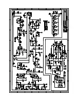
Страница 5: ...BTA850C WIRING DIAGRAM...
Страница 6: ...Not applicable to the TA850C BTA850FH TA850C BTA850FH are 2 Ohm products...


