


GENERAL FITTING GUIDE
LOW LEVEL FLUSH PIPE KIT
GUARANTEE & AFTERCARE
When installing or using tools, extra care must be taken to avoid damaging the finish or fitting. To maintain the appearance, please ensure it is cleaned regularly using a clean soft damp cloth only. Abrasive cleaners or detergents must not be used as
they may cause surface deterioration.
The company provides a guarantee against faulty material or manufacture excluding serviceable parts, providing they have been installed, cared for and used in accordance with our instructions. Any misuse will invalidate your guarantee
IMPORTANT
Flush out all impurities in the cistern prior to installation
.
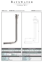
ASSEMBLY DIAGRAM
Ensure you have all of the parts before proceeding.
INLET VALVE SPECIFICATIONS
Water Temperature: 2°C - 45°C
Water Pressure: 0.2 Bar to 8 Bar
ASSEMBLY INSTRUCTIONS
FLUSH VALVE SPECIFICATIONS
Full Flush: 6L
3. Insert the flush pipe into the bottom of the cistern and tighten the compression unit.
To ensure a water tight seal use PTFE tape.
Low Level Cistern
Flush Valve Base
Rubber Conical Washer
Compression Nut
Move the cover over the compression fitting and move the 'O' Ring so it stays in position.
Chrome Cover
Cover 'O' Ring
Low Level Fush Pipe
1. Mount the Cistern to the wall so that the top of the cistern is 1100mm off the floor.
Secure to the wall using fixings suitable for the installation at hand (not supplied).
Rubber Compression Washer
Compression Nut
4. Insert the flush pipe and flush cone into the inlet hole on the Pan.
Ensure the pipe is fitted securely into the Pan.
Use a small bead of silicone to hold the cover in place.
MAKING PLUMBING CONNECTIONS
Connect the soil pipe and ensure it is adequately sealed around the Toilet Pan outlet to prevent
leakage.
tape before connecting the water supply.
Chrome Cover
Flush Cone
Cover 'O' Ring
Low Level Fush Pipe
After connecting the water supply to the inlet valve check that the inlet valve components do not touch
the internal walls of the cistern and the
float can move freely up and down.
Check all connections are secure and a soil pipe is fitted before testing the flush.
AFTER CARE
2. Put the parts labelled onto the flush pipe according to the diagram.
(Note: Flush Pipe, 'O' Ring and Chrome Cover are supplied separate to cistern in kit)
DO NOT introduce caustic chemical substances (e.g. containing chlorine compounds or similar).
Do not overtighten the supply to the inlet valve as this could damage the inlet valve causing leakage.
1100
The inlet valve has a threaded connector. It is recommended that this thread is wrapped in PTFE
These can damage the valve components and cause failure.
Flush Cone


